NX20 20-Channel 2.
EN NOTICE All instructions, warranties and other collateral documents are subject to change at the sole discretion of Horizon Hobby, LLC. For upto-date product literature, visit horizonhobby.com or towerhobbies.com and click on the support or resources tab for this product.
EN CHARGING WARNINGS WARNING: Failure to exercise caution while using this product and comply with the following warnings could result in product malfunction, electrical issues, excessive heat, FIRE, and ultimately injury and property damage. • NEVER LEAVE CHARGING BATTERIES UNATTENDED. • NEVER CHARGE BATTERIES OVERNIGHT. • Never attempt to charge dead, damaged or wet battery packs. • Never attempt to charge a battery pack containing different types of batteries.
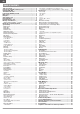
EN TABLE OF CONTENTS Table of Contents......................................................................... 4 Charging the Lithium Ion Battery Pack....................................... 5 Updating with WiFi...................................................................... 5 Transmitter Functions................................................................. 6 Powering the NX20 On and Off.................................................... 7 Main Screen............................................
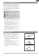
EN CHARGING THE LITHIUM ION BATTERY PACK For optimum charging results, the built-in charger requires a USB power supply capable of at least 2-3A output. Using a power supply with a lower output will result in very long charge times or the transmitter not charging if it is powered on while attempting to charge. The first time the transmitter is charged, the charge time may be 6-7 hours. Charge the transmitter when the low battery alarm sounds.
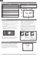
EN TRANSMITTER FUNCTIONS 1 2 3 4 5 6 7 8 9 10 6 Function Elevator Trim (Mode 2, 4) Throttle Trim (Mode 1, 3) R Trimmer R Knob Switch E Switch H Switch G Switch F Throttle Tension Adjustment Throttle Ratchet Adjustment (Mode 1, 3) Gimbal Travel Limiter Access Panel Mode Change Screw 11 12 13 14 15 16 17 18 19 20 Function Throttle/Aileron Stick (Mode 1) Elevator/Aileron Stick (Mode 2) Throttle/Rudder Stick (Mode 3) Elevator/Rudder Stick (Mode 4) Left/Right Gimbal Stick Tension Adjustment Up/Down Gimbal
EN 1 2 3 4 5 6 Function Switch I/ Bind Switch A Left Lever Mounting for CSRF Micro USB Connector Memory Card Opening 7 8 9 10 11 12 Function Battery Cover Data Port Audio Port Right Lever Switch H Antenna Rotation Tension POWERING THE NX20 ON AND OFF 1. Press and hold the Spektrum Logo for several seconds to turn ON the NX20. 2. Press and hold the power button for about 4 seconds to power OFF the NX20.
EN MAIN SCREEN Function 1 Model Name 2 DSMX/DSM2 If not shown, this indicates not bound 3 Displays throttle position Digital Battery Voltage (an alarm sounds and the screen flashes 4 when battery charge gets down to 3.2V for a Li Ion battery.
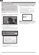
EN INTERNAL MEMORY The internal memory may be accessed via the USB port on the transmitter to enable the following tasks: • Update Spektrum AirWare software in the transmitter • Install/Update sound files • Back up models for safe keeping • Import/Export Color Palettes To connect to the internal memory: 1. Connect a Micro USB cable to your PC and the micro USB connector on the back of the transmitter. 2.
EN MEMORY CARD FUNCTIONS Update Spektrum AirWare™ Software NOTICE: The orange LED Spektrum bars flash and a status bar appears on the screen when Spektrum AirWare software updates are installing. Never power off the transmitter when updates are installing. Doing so may damage the system files. NOTICE: Before installing any Spektrum AirWare files, always Export All Models to an Memory card separate from the Memory card containing the update. The update may erase all model files.
Audio Events Trainer VTX Setup Analog Switch Setup EN Function Bar Digital Switch Setup Start Timer Center Tone System Setup Sound Utilities MODEL TYPE PROGRAMMING GUIDE Monitor System Settings Menu options show up on model type selection. These menu options varyWiFi between Model Types (Airplane, Helicopter,Sailplane and Utilities Multirotor), but are identical for all models in that type.
EN SYSTEM SETUP Enter the System Setup menu to define baseline settings for your model such as what type of aircraft, wing type, flight mode setup, etc. The options chosen in the system menu configures the function list for the chosen model number for your requirements. Some options, such as the flap menu, will not appear at all in the function list until they are selected within the System Setup menu. Press and hold the scroll wheel while powering on the transmitter to show the System Setup list.
EN Model Name Model Name enables you to assign a custom name to the current model memory. Model names can include up to 20 characters, including spaces. To add letters to a Model Name: 1. Scroll to the desired letter position and press the scroll wheel once. A flashing box appears. 2. Scroll left or right until the desired character appears. Press the scroll wheel once to save the character. 3. Scroll to the next desired letter position. Repeat Steps 1 and 2 until the Model Name is complete.
EN Flight Mode Setup Enables you to assign custom names to the Flight Mode positions. Flight Mode names can include up to 20 characters, including spaces. To change the Flight Mode name: 1. Scroll to the Flight Mode name you wish to change and press the scroll wheel. 2. Scroll to the character position you wish to change and press the scroll wheel once. A flashing box appears. 3. Scroll left or right until the desired character appears. Press the scroll wheel once to save the character.
EN Trim Setup Use the Trim Setup screen to change the size of the trim step and the trim type. Trim Step Adjusting the trim step value determines how many “clicks” of trim you input each time you press the trim button. Changing the trim step value to 0 disables the trim for the channel. To change the trim step value: 1. Scroll to the trim step channel you wish to change. 2. Select the trim step value and scroll left or right to change the value. 3. Press the scroll wheel to save the selection.
EN Model Utilities In the Model Utilities function you can create a new model, delete a model, copy a model, reset a model to default settings and sort the model list. Create New Model Use this selection to create a new model in the model select list. 1. Select Create New Model. Within this screen, you will have the option to create a new model or cancel. 2. Select the model type. Choose the aircraft image to define the model type for a blank model file, or select Template to load a template file.
EN Copy Model The Model Copy menu enables you to duplicate model programming from one Model List location to another. Use Model Copy to: • Save a default model copy before experimenting with programming values • Expedite programming for a model using a similar programming setup IMPORTANT: Copying a model program from one model memory to another will erase any programming in the “To” model memory. To copy model programming: 1. Make sure the model program you wish to copy is active.
EN Telemetry Installing the optional telemetry module and sensors enables the display of aircraft performance data on the transmitter screen. You can also enable Data Logging to save a telemetry file on the Memory card and view the data in the Spektrum STi™ mobile application or other TLM file viewers. Telemetry Settings Display Telemetry display options include: Tele: When you press the scroll wheel, the Telemetry screens appear and the Main Screen is disabled.
EN Preflight Setup The Preflight Setup menu option enables you to program a pre-flight checklist that appears each time you power on the transmitter or when you select a new model memory. Each item on the list must be confirmed before you can access the Main Screen. Frame Rate The Frame Rate menu enables you to change the frame rate and modulation mode. Select the option you wish to change and press the scroll wheel. You must use digital servos if you select 11ms frame rate.
EN Trainer All options related to programming and using the trainer functions are controlled with the Trainer menu. Three options are available in the trainer menu: • Wired Trainer • Wireless Trainer • Trainer Alerts Wired Trainer and Wireless Trainer have similar options when connecting two transmitters for the purpose of training a student pilot.
EN Instructor Transmitter Configuration 1. Select the type of trainer mode for the application (Wired or Wireless, Programmable Instructor or Pilot Link Instructor). 2. Choose whether or not to enable Instructor Over-Ride. This setting defines how the instructor can resume control from the student. When enabled, the instructor must not move the sticks when the student is given control. Moving the sticks or moving the selected trainer switch will return control to the instructor.
EN Center Tone The Center Tone menu allows you to select or change the sound the NX20 makes when the selected control is at neutral. 1. Select a switch from the list. 2. Select the desired alarm. The choices are Inh, Tone, Vibe, Tone/Vibe, Voice, Voice/Vibe. 3. If either of the Voice alarms are chosen, select from the available spoken sound list.
EN Brightness The Brightness field adjusts the backlight appearance time and brightness. The brightness time options are: On: The backlight is always on. Set Time: The backlight is on for 3, 10, 20, 30, 45 or 60 seconds before automatically dimming. Press the scroll wheel once to turn the backlight on. The backlight percentage adjusts the backlight intensity and it is adjustable in 10% increments from 10% (darker) to 100% (brighter). Mode* To change the gimbal stick mode: 1.
EN Extra Settings The Extra Settings screen enables you to: • Turn sounds off or on • Change the appearance of the trim indicators System Sounds Scrolling to System Sounds and pressing the scroll wheel turns sounds on (Active) or off (Inhibit). You may disable all sounds by changing the volume to 0. Vibrator Intensity Adjustment Adjust this value to change the intensity of the built-in vibrator. Trim Style Trim style changes the shape of the trim indicators on the Main Screen.
EN Power Sounds Select from a variety of sound options the system will play at power up and power down. Factory Reset Select this option to reset the NX20 back to factory settings. Choosing this option will wipe out any settings and all models that have been set in the NX20 programming. Calibrate The Calibration screen stores the potentiometer endpoints for all proportional controls. It is mandatory to complete the calibration after changing the stick mode selection. To Calibrate the Transmitter: 1.
EN Transfer Memory Card This menu enables you to: • Import (copy) models from another NX20 transmitter • Export (transfer) models to another NX20 transmitter • Update Spektrum AirWare™ software in the transmitter • Install/Update sound files • Take screen shots • Import or export color palettes • Select from internal or external memory locations Model Import/Export Import All Models Ensure the models currently stored in the internal transmitter memory are saved to a micro memory card separate from the tr
EN Importing/Exporting Color Palettes Import Palette You can use the Import Palette option to load a Palette from your memory card. 1. Load your color palette onto a memory card or the internal memory. 2. In the Transfer Memory Card menu, scroll to Options and press the scroll wheel once. 3. Select the memory card location (Internal or external) where your Palette has been loaded. 4. Scroll to Palette Import/Export and select Import Color Palette. 5.
EN About / Regulatory Serial Number The Serial Number screen displays the transmitter serial number and Spektrum AirWare software version. Reference the Serial Number screen any time you need to register your transmitter or update the Spektrum AirWare software from the Spektrum Community website.
EN FUNCTION LIST Once you have selected the model number you want to use and have defined the aircraft type, wing and tail type and other details in the System Setup menu, use the Function list to define the details specific to your model’s setup such as servo travel, reversing, mixing, etc. The Main Screen appears when you power on the transmitter. Press the scroll wheel once to display the Function List.
EN Speed The Speed menu enables you to slow the response time on any individual channel (such as retracts). The Speed is adjustable in the following ranges: • Nor (No Delay) – 0.9s in 0.1 second increments • 1s – 2s in 0.2-second increments • 2s – 8s in 1-second increments To adjust the Speed: 1. Scroll to the channel you wish to adjust and press the scroll wheel. 2. Scroll left or right to adjust the speed and press the scroll wheel to save the selection. Absolute (Abs.) Travel The Abs.
EN Throttle Cut (Acro and Heli Types Only) The Throttle Cut menu option enables you to assign a switch position to stop an engine or motor. Throttle Cut activates regardless of Flight Mode. When you activate Throttle Cut, the throttle channel moves to the pre-programmed position (normally Off). You may need to use a negative value to move the Throttle channel to the off position. CAUTION: Always test the model after making adjustments to make sure the model responds to controls as desired.
EN Mixing Mixing allows control input for a channel to affect more than one channel at a time. Mixing functions support: • Mixing a channel to another channel. • Mixing a channel to itself. • Assigning offset to a channel. • Linking primary to secondary trim.
EN Curve Mix If you want to be able to assign the output channel to respond on a curve or act as a switch, the Curve mix option will enable you to move the output channel to any value at up to 7 points along the travel of the input channel. Below the curve values, select a channel for master control on the left and slave on the right. For example, Throttle > Rudder makes Throttle the master channel and Rudder the slave channel.
EN TIP: If you need to use a 3-position switch, you must assign one direction to two adjacent switch positions—e.g., 0 and 1. Assign the opposite direction to the third switch position. 3. Assign the timing for the Forward and Reverse directions as desired. There is no delay when you use the Nor option. You may also select a delay time between 0 and 30 seconds. 4. Assign names for each sequencer function as desired. 5. Select either Step (S) or Proportional (P) for the Sequencer output.
EN Timer The NX20 Timer function allows you to program a countdown timer or stop watch (count up timer) to display on the main screen. An alarm sounds when the programmed time is reached. You can program the timer to start using the assigned switch position or automatically when throttle is raised above a programmed position. Two internal timers are available that show run time for a specific model displays on the Main Screen. A total system timer is also available.
EN Audio Events For compatible video transmitters, this menu can select the options directly from your NX20. Set the Power level and frequency of your video transmitter, and select Send to make the change. Switch Changes Use the switch change report to call out what your switch positions are. With this menu you can assign audio reports for events such as changing modes or rates, retract position, flap position, etc.
EN My List Setup My List gives you quick access to a short list of commonly used menu items you create. • Press the Function button to open My List • Scroll to select the menu you want, and click to choose that option • CLEAR will take you to the first entry on the list • BACK or FUNC will exit to original screen IMPORTANT: If a menu option is not available on the Function List such as due to a Wing/Tail type change, it will not be selectable from the My List.
EN The following menu options are only available when they are enabled from the Model Type screen. V-Tail Differential Only available in Sailplane Type when V-Tail A or V-Tail B is active. See SAIL (Sailplane) section for set up. Camber Preset Only available in Sailplane Type when a 2+ aileron wing type is selected. See SAIL (Sailplane) section for set up. Camber System Only available in Sailplane Type when a 2+ aileron wing type is selected. See SAIL (Sailplane) section for set up.
EN ACRO (AIRPLANE) CAUTION: Always do a Control Test of your model with the transmitter after programming to make sure your model responds as desired. NOTICE: Refer to your airplane manual for recommended control throws. Aircraft Type Use the Aircraft Type Screen to select wing and tail types to match your airplane model. Diagrams and setup names show on the transmitter screen to show the available setups. Select wing and tail types before doing any other programming. Refer to spektrumrc.
EN Elevon Servo Control The possible servo reversing options for a delta wing model are: Aileron Elevator Normal Normal Reverse Reverse Reverse Normal Reverse Normal TIP: If you test all servo reversing options and the control surfaces do not move in the correct direction, change the Elevon wing type in the System Setup list from Elevon A to Elevon B.
EN Differential If you enable a wing type with two aileron servos, the function menu will have a Differential menu added. This feature is intended for you to be able to set the ailerons for equal travel, or to be able to set them for more up travel than down travel, depending on your aircraft and intentions. To use the Differential System: 1. Select the switch you want to use. If you want to use one setting full-time, set the Switch to ON. 2. Set your values to achieve your desired results.
EN HELI (HELICOPTER) CAUTION: Always do a Control Test of your model with the transmitter after programming changes to make sure your model responds as desired. NOTICE: Refer to your helicopter, gyro and governor manuals for programming recommendations. To change the Helicopter Icon: From the Collective Type Screen, select NEXT at the bottom right of the screen. This will access the Heli image screen. Scroll to the icon and click once. Roll the scroll wheel left or right for optional icons.
EN Swashplate The Swashplate menu option enables you to adjust the following: • Swashplate Mix • Exponential • E-Ring • Elevator Compensation Use positive or negative Swashplate mix values as needed for correct direction response of the helicopter. Before making adjustments to the Swashplate mix, make sure the throttle/collective pitch input moves the entire swashplate up or down. If the servos are not moving in the same direction, reverse them as necessary in the Servo Setup menu option.
EN SAIL (SAILPLANE) CAUTION: Always do a Control Test of your model with the transmitter after programming to make sure your model responds as desired. NOTICE: Refer to your sailplane manual for recommended control throws. Sailplane Type Use the Sailplane Type Screen to select wing and tail types to match your sailplane model. Diagrams and setup names show on the transmitter screen to show the available setups. Refer to spektrumrc.
EN SAIL Mixing For each of these mixes, you can program each flight mode with different mix values or at 0% if no mix is desired for that specific flight mode. Programming values include independent control of the direction and amount a slave surface moves in relationship to the master surface. Aileron to Rudder The Aileron to Rudder mix is commonly used for coordinated turns.
EN MULTI (MULTIROTOR) CAUTION: Always do a Control Test of your model with the transmitter after programming to make sure your model responds as desired. NOTICE: Refer to your multirotor manual for programming recommendations. The Aircraft Options menu allows you to select a camera gimbal axis. Select None, 1–Axis, 2–Axis or 3–Axis from the Camera Options box. The model icon can be changed by selecting the icon and scrolling left or right to select.
EN Motor Cut The Motor Cut menu option enables you to assign a switch position to stop the motor. Motor Cut activates regardless of Flight Mode. When you activate Motor Cut, the ALT channel moves to the preprogrammed position (normally Off). You may need to use a negative value to move the ALT channel to the off position. CAUTION: Always test the model after making adjustments to make sure the model responds to controls as desired.
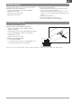
EN PHYSICAL TRANSMITTER ADJUSTMENTS The NX20 has all the physical transmitter adjustments located around the gimbal face of each gimbal. This arrangement allows for quick and easy adjustments with out taking the back cover off or removing any plugs to access adjustment screws.
EN Ratcheted Throttle – Smooth Throttle Adjustment Ratchet 1. Locate the throttle strap adjustment screws on both gimbals. The ratchet set screw engages a serrated section on the gimbal for a ratcheted throttle, while the tension set screw engages a strap for smooth tension on the gimbal. 2. To engage the throttle ratchet turn the ratchet set screw clockwise until the ratchet engages. 3. To disengage the throttle ratchet turn the screw counter clockwise until the gimbal moves freely. Smooth Tension 1.
EN TROUBLESHOOTING GUIDE Problem Possible Cause Transmitter too near aircraft during binding process Aircraft will not bind (during binding) to transmitter Aircraft or transmitter is too close to large metal object The bind plug is not installed correctly in the bind port Flight battery/Transmitter battery charge is too low Transmitter is a NX20 EU version and receiver is DSM2 Transmitter too near aircraft during linking process Aircraft or transmitter is too close to large metal object Aircraft will n
EN 1-YEAR LIMITED WARRANTY What this Warranty Covers Horizon Hobby, LLC, (Horizon) warrants to the original purchaser that the product purchased (the “Product”) will be free from defects in materials and workmanship for a period of 1 year from the date of purchase.
EN WARRANTY AND SERVICE CONTACT INFORMATION Country of Purchase United States of America EU Horizon Hobby Contact Information Horizon Service Center servicecenter.horizonhobby.com/RequestForm/ (Repairs and Repair Requests) productsupport@horizonhobby.com Horizon Product Support (Product Technical Assistance) 877-504-0233 websales@horizonhobby.com Sales 800-338-4639 Horizon Technischer Service service@horizonhobby.
EN COMPLIANCE INFORMATION FOR THE EUROPEAN UNION EU Manufacturer of Record: EU Compliance Statement: Horizon Hobby, LLC Spektrum NX20 Transmitter Only 2904 Research Road (SPMR20500EU); Hereby, Horizon Hobby, LLC Champaign, IL 61822 USA declares that the device is in compliance with the following: EU Radio Equipment Directive 2014/53/EU; RoHS 2 EU Importer of Record: Directive 2011/65/EU; RoHS 3 Directive - Amending 2011/65/EU Horizon Hobby, GmbH Annex II 2015/863.
EN 54 © 2022 Horizon Hobby, LLC DSM, DSM2, DSMX, the DSMX logo, Bind-N-Fly, BNF, the BNF logo, Spektrum AirWare, STi, ModelMatch, AS3X, SmartSafe, and the Horizon Hobby logo are trademarks or registered trademarks of Horizon Hobby, LLC. The Spektrum trademark is used with permission of Bachmann Industries, Inc. US 7,391,320. US 9,930,567. US 10,419,970. US 10,849,013. Other patents pending. www.spektrumrc.com Created 08/2022 404900.