SR6100AT AVC Telemetry Receiver Instruction Manual AVC-Telemetrieempfänger-Bedienungsanleitung Manuel d’instructions du récepteur AVC avec télémétrie Manuale di istruzioni del ricevitore AVC con telemetria 1
EN NOTICE All instructions, warranties and other collateral documents are subject to change at the sole discretion of Horizon Hobby, LLC. For up-to-date product literature, visit horizonhobby.com or towerhobbies.com and click on the support or resources tab for this product.
EN TABLE OF CONTENTS SR6100AT Receiver Diagram ....................................................................... 4 Powering the receiver with a separate receiver pack ..................................... 4 Powering the receiver with an ESC ............................................................... 4 SMART Throttle ........................................................................................... 4 AVC Receiver Installation ...............................................................
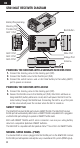
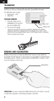
EN SR6100AT RECEIVER DIAGRAM Battery/Programming Steering Port Throttle Port AUX 1 Port AUX 2 Port AUX 3 Port AUX 4 Port Bind Button XBus Port Voltage Port Antenna POWERING THE RECEIVER WITH A SEPARATE RECEIVER PACK 1. Connect the steering servo to the steering port (STR) 2. Connect the throttle servo to the throttle port (THR) 3. Connect the switch harness and a 3.5V–9.6V battery to the battery (BATT) port to power on receiver. POWERING THE RECEIVER WITH AN ESC 1.
EN NOTICE: Do not connect a dedicated receiver battery to the receiver along with an ESC (with a BEC, a feature which most ESCs include). When an ESC is turned on it will provide the receiver with regulated power from the main battery through the throttle connection. The ESC, battery and/or receiver may be damaged if the receiver is also connected to a dedicated receiver battery. This does not apply to an ESC which does not have a BEC.
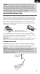
EN TELEMETRY In addition to SMART Throttle, the SR6100AT Telemetry Receiver features two integrated telemetry ports that are compatible with telemetry capable DSMR transmitters. The Telemetry ports include: • Voltage (0V – 51V) • XBus Port VOLTAGE SENSOR • Plug the voltage sensor (SPMA9570) into the VOLT XBus Port port on the SR6100AT. Voltage Port • To connect the voltage sensor to your vehicle, typically it would be soldered to the battery connector.
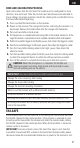
EN BIND AND CALIBRATION PROCESS Upon initial setup after the first bind, the model must be configured for servo direction, trim and travel. Then the receiver must be rebound and calibrated to those settings for proper operation. Center the steering trim and throttle trim on the transmitter before beginning. 1. Press and hold the bind button on the receiver. 2. Power on the receiver. The orange LED flashes, indicating the receiver is in bind mode. Release the bind button after the orange LED illuminates. 3.
EN DISABLING AVC TECHNOLOGY AVC may be disabled during binding. 1. Connect power to the receiver and quickly press and release the bind button three times (within 1.5 seconds). 2. Press and hold the bind button and to put the receiver in bind mode. release the buton when the LED starts to flash rapidly, indicating it is in bind mode. When the AVC system has been disabled, the LED on the receiver will show three flashes upon power up, and then remain lit.
EN AUX CHANNELS AND AVC TECHNOLOGY When AVC is active, the SR6100AT receiver will use the AUX 1 and AUX 2 channels for gain control. AUX 1 and AUX 2 should be allocated for AVC when AVC is active. This is done automatically when the AVC menu is selected in your transmitter, but if you are not using the AVC menu, AUX1 or AUX2 should not be used for other mixes or to control other applications (servos, etc.
EN WHAT IS HEADING HOLD? Heading hold maintains the vehicle’s direction. It is normal to see the wheels steer in the same direction the vehicle was last pointed. If a vehicle with AVC technology is lifted off the ground and turned from side to side, the wheels will steer in an effort to get back to the original heading. When driving, heading hold only works when the steering wheel is left straight. The moment you begin to turn the wheel, heading hold turns off.
EN CHANGING BATTERY VOLTAGE WHEN USING AVC If you increase voltage going to your vehicle, the maximum steering gain setting will have to be reduced. At the same time, when increasing voltage increased throttle gain will help manage the extra power. For example: If a truck set up for 2S is upgraded to 3S, the truck may oscillate at high speeds on 3S, requiring steering gain to be reduced. Throttle gain will have a bigger effect on 3S, so increasing throttle gain may be beneficial.
EN 2.
EN AVC TROUBLESHOOTING GUIDE Problem Vehicle Oscillates (wobbles or shakes) at high speeds Vehicle responds strangely to controls Receiver won’t finish the calibration Driver expects AVC should be turned off, but it is still turned on Possible Cause Solution Steering gain is too high Reduce steering gain Receiver not properly calibrated Vehicle setup changed after calibration Confirm servo direction and travel are correct, then re-bind and recalibrate the receiver Confirm the receiver is truly Receiv
EN 1-Year Limited Warranty What this Warranty Covers - Horizon Hobby, LLC, (Horizon) warrants to the original purchaser that the product purchased (the “Product”) will be free from defects in materials and workmanship for a period of 1 year from the date of purchase.
EN Inspection or Services If this Product needs to be inspected or serviced and is compliant in the country you live and use the Product in, please use the Horizon Online Service Request submission process found on our website or call Horizon to obtain a Return Merchandise Authorization (RMA) number. Pack the Product securely using a shipping carton. Please note that original boxes may be included, but are not designed to withstand the rigors of shipping without additional protection.
EN Warranty, Service and Customer Service Contact Information Country of Purchase Horizon Hobby Horizon Service Center (Repairs and Repair Requests) United States of America Horizon Product Support (Product Technical Assistance) Sales Horizon Technischer Service EU Sales: Horizon Hobby GmbH Contact Information Address servicecenter. horizonhobby.com/ RequestForm/ productsupport@ 2904 Research Rd. horizonhobby.com. Champaign, Illinois, 877-504-0233 61822 USA websales@ horizonhobby.
EN generates, uses and can radiate radio frequency energy and, if not installed and used in accordance with the instructions, may cause harmful interference to radio communications. However, there is no guarantee that interference will not occur in a particular installation.
IT © 2019 Horizon Hobby, LLC. AVC, the SMART technology logo, Firma, DSM, DSM2, DSMR, Hangar 9, QuickConnect, ModelMatch, SmartSafe and the Horizon Hobby logo are trademarks or registered trademarks of Horizon Hobby, LLC. The Spektrum trademark is used with permission of Bachmann Industries, Inc. US 9,320,977. 60061.