SR6100AT AVC Telemetry Receiver Instruction Manual AVC-Telemetrieempfänger-Bedienungsanleitung Manuel d’instructions du récepteur AVC avec télémétrie Manuale di istruzioni del ricevitore AVC con telemetria 1
EN NOTICE All instructions, warranties and other collateral documents are subject to change at the sole discretion of Horizon Hobby, LLC. For up-to-date product literature, visit horizonhobby.com or towerhobbies.com and click on the support or resources tab for this product.
EN TABLE OF CONTENTS SR6100AT Receiver Diagram ....................................................................... 4 Powering the receiver with a separate receiver pack ..................................... 4 Powering the receiver with an ESC ............................................................... 4 SMART Throttle ........................................................................................... 4 AVC Receiver Installation ...............................................................
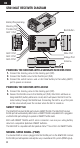
EN SR6100AT RECEIVER DIAGRAM Battery/Programming Steering Port Throttle Port AUX 1 Port AUX 2 Port AUX 3 Port AUX 4 Port Bind Button XBus Port Voltage Port Antenna POWERING THE RECEIVER WITH A SEPARATE RECEIVER PACK 1. Connect the steering servo to the steering port (STR) 2. Connect the throttle servo to the throttle port (THR) 3. Connect the switch harness and a 3.5V–9.6V battery to the battery (BATT) port to power on receiver. POWERING THE RECEIVER WITH AN ESC 1.
EN NOTICE: Do not connect a dedicated receiver battery to the receiver along with an ESC (with a BEC, a feature which most ESCs include). When an ESC is turned on it will provide the receiver with regulated power from the main battery through the throttle connection. The ESC, battery and/or receiver may be damaged if the receiver is also connected to a dedicated receiver battery. This does not apply to an ESC which does not have a BEC.
EN TELEMETRY In addition to SMART Throttle, the SR6100AT Telemetry Receiver features two integrated telemetry ports that are compatible with telemetry capable DSMR transmitters. The Telemetry ports include: • Voltage (0V – 51V) • XBus Port VOLTAGE SENSOR • Plug the voltage sensor (SPMA9570) into the VOLT XBus Port port on the SR6100AT. Voltage Port • To connect the voltage sensor to your vehicle, typically it would be soldered to the battery connector.
EN BIND AND CALIBRATION PROCESS Upon initial setup after the first bind, the model must be configured for servo direction, trim and travel. Then the receiver must be rebound and calibrated to those settings for proper operation. Center the steering trim and throttle trim on the transmitter before beginning. 1. Press and hold the bind button on the receiver. 2. Power on the receiver. The orange LED flashes, indicating the receiver is in bind mode. Release the bind button after the orange LED illuminates. 3.
EN DISABLING AVC TECHNOLOGY AVC may be disabled during binding. 1. Connect power to the receiver and quickly press and release the bind button three times (within 1.5 seconds). 2. Press and hold the bind button and to put the receiver in bind mode. release the buton when the LED starts to flash rapidly, indicating it is in bind mode. When the AVC system has been disabled, the LED on the receiver will show three flashes upon power up, and then remain lit.
EN AUX CHANNELS AND AVC TECHNOLOGY When AVC is active, the SR6100AT receiver will use the AUX 1 and AUX 2 channels for gain control. AUX 1 and AUX 2 should be allocated for AVC when AVC is active. This is done automatically when the AVC menu is selected in your transmitter, but if you are not using the AVC menu, AUX1 or AUX2 should not be used for other mixes or to control other applications (servos, etc.
EN WHAT IS HEADING HOLD? Heading hold maintains the vehicle’s direction. It is normal to see the wheels steer in the same direction the vehicle was last pointed. If a vehicle with AVC technology is lifted off the ground and turned from side to side, the wheels will steer in an effort to get back to the original heading. When driving, heading hold only works when the steering wheel is left straight. The moment you begin to turn the wheel, heading hold turns off.
EN CHANGING BATTERY VOLTAGE WHEN USING AVC If you increase voltage going to your vehicle, the maximum steering gain setting will have to be reduced. At the same time, when increasing voltage increased throttle gain will help manage the extra power. For example: If a truck set up for 2S is upgraded to 3S, the truck may oscillate at high speeds on 3S, requiring steering gain to be reduced. Throttle gain will have a bigger effect on 3S, so increasing throttle gain may be beneficial.
EN 2.
EN AVC TROUBLESHOOTING GUIDE Problem Vehicle Oscillates (wobbles or shakes) at high speeds Vehicle responds strangely to controls Receiver won’t finish the calibration Driver expects AVC should be turned off, but it is still turned on Possible Cause Solution Steering gain is too high Reduce steering gain Receiver not properly calibrated Vehicle setup changed after calibration Confirm servo direction and travel are correct, then re-bind and recalibrate the receiver Confirm the receiver is truly Receiv
EN 1-Year Limited Warranty What this Warranty Covers - Horizon Hobby, LLC, (Horizon) warrants to the original purchaser that the product purchased (the “Product”) will be free from defects in materials and workmanship for a period of 1 year from the date of purchase.
EN Inspection or Services If this Product needs to be inspected or serviced and is compliant in the country you live and use the Product in, please use the Horizon Online Service Request submission process found on our website or call Horizon to obtain a Return Merchandise Authorization (RMA) number. Pack the Product securely using a shipping carton. Please note that original boxes may be included, but are not designed to withstand the rigors of shipping without additional protection.
EN Warranty, Service and Customer Service Contact Information Country of Purchase Horizon Hobby Horizon Service Center (Repairs and Repair Requests) United States of America Horizon Product Support (Product Technical Assistance) Sales Horizon Technischer Service EU Sales: Horizon Hobby GmbH Contact Information Address servicecenter. horizonhobby.com/ RequestForm/ productsupport@ 2904 Research Rd. horizonhobby.com. Champaign, Illinois, 61822 USA 877-504-0233 websales@ horizonhobby.
EN generates, uses and can radiate radio frequency energy and, if not installed and used in accordance with the instructions, may cause harmful interference to radio communications. However, there is no guarantee that interference will not occur in a particular installation.
DE HINWEIS Alle Anweisungen, Garantien und anderen zugehörigen Dokumente können im eigenen Ermessen von Horizon Hobby, LLC jederzeit geändert werden. Aktuelle Produktliteratur finden Sie unter www.horizonhobby.com oder www.towerhobbies. com im Support-Abschnitt für das Produkt.
DE TABLE OF CONTENTS Grafik Empfänger SR6100AT ................................................................... 20 Stromversorgung des Empfängers mit einem separaten Empfängerpaket ... 20 Stromversorgung des Empfängers mit einem Geschwindigkeitsregler ......... 20 SMART Throttle: ...................................................................................... 20 Installation des AVC-Empfängers .............................................................. 21 Telemetrie .............................
DE GRAFIK EMPFÄNGER SR6100AT Akku/Programmierung Steueranschluss Gasanschluss AUX-1-Anschluss AUX-2-Anschluss AUX-3-Anschluss AUX-4-Anschluss Bindungsschalter XBus-Anschluss Spannungsanschluss Antenne STROMVERSORGUNG DES EMPFÄNGERS MIT EINEM SEPARATEN EMPFÄNGERPAKET 1. Die Servolenkung mit dem Lenkungsanschluss (STR) verbinden 2. Den Gasservo mit dem Gasanschluss (THR) verbinden 3. Um den Empfänger einzuschalten, das Schalterkabel und einen 3,5 V – 9,6 V Akku an den Akku-Anschluss (BATT) anschließen.
DE HINWEIS: Ein dedizierter Empfängerakku darf nicht zusammen mit einem Geschwindigkeitsregler (mit einem BEC, eine Funktion, die die meisten Geschwindigkeitsregler beinhalten) an den Empfänger angeschlossen werden. Wenn ein Geschwindigkeitsregler eingeschaltet wird, versorgt er den Empfänger über den Gasanschluss mit geregelter Spannung vom Hauptakku.
DE TELEMETRIE Zusätzlich zu SMART Throttle verfügt der SR6100AT-Telemetrieempfänger über zwei integrierte Telemetrieanschlüsse, die mit telemetriefähigen DSMR-Sendern kompatibel sind. Bestandteile der Telemetrieanschlüsse: • Spannung (0 V – 51 V) • XBus-Anschluss SPANNUNGSSENSOR • Den Spannungssensor XBus-Anschluss (SPMA9570) an den VOLTSpannungsanschluss Anschluss des SR6100AT anschließen. • Um den Spannungssensor an das Fahrzeug anzuschließen, wird er üblicherweise an den Akkustecker gelötet.
DE BINDUNGS- UND KALIBRIERUNGSVORGANG Bei der Erstinbetriebnahme nach der ersten Bindung müssen Servolaufrichtung, Trimmung und Verfahrweg des Modells konfiguriert werden. Damit er ordnungsgemäß funktioniert, muss der Empfänger anschließend den Einstellungen entsprechend erneut gebunden und kalibriert werden. Vorher die Lenkungs- und die Gastrimmung am Empfänger zentrieren. 1. Halten Sie den Bindungsschalter am Sender gedrückt. 2. Den Empfänger einschalten.
DE DEAKTIVIERUNG DER AVC-TECHNOLOGIE Während des Bindens kann AVC deaktiviert werden. 1. Den Empfänger mit Strom versorgen und die Bindungstaste dreimal (innerhalb von 1,5 Sekunden) kurz drücken und wieder loslassen. 2. Um den Empfänger in den Bindungsmodus zu versetzen, die Bindungstaste gedrückt halten und loslassen, sobald der Bindungsmodus durch schnelles Blinken der LED angezeigt wird.
DE AUX-KANÄLE UND AVC-TECHNOLOGIE Wenn AVC aktiv ist, verwendet der SR6100AT-Empfänger die Kanäle AUX 1 und AUX 2 zur Verstärkungsregelung. AUX 1 und AUX 2 sind AVC zuzuordnen, wenn AVC aktiv ist. Dies geschieht automatisch, wenn das AVC-Menü im Sender ausgewählt ist. Wird das AVCMenü jedoch nicht verwendet, sollten AUX 1 oder AUX 2 nicht für andere Mischungen oder zur Steuerung anderer Anwendungen (Servos usw.) verwendet werden.
DE WAS IST HEADING HOLD? Heading Hold wird die gewählte Richtung des Fahrzeugs aufrechterhalten. Es ist normal, wenn die Räder in dieselbe Richtung steuern, in die sie zuletzt ausgerichtet waren. Wird ein Fahrzeug mit AVC-Technologie hochgehoben und von Seite zu Seite gedreht, dann werden die Räder sich im Bemühen bewegen, wieder in die ursprüngliche Fahrtrichtung zu gelangen. Beim Fahren funktioniert der Heading Hold nur, wenn das Steuerrad gerade belassen wird.
DE AKKU-SPANNUNG ÄNDERN Ist die Spannung erhöht, so muss die maximale Einstellung des Lenkzuwachses reduziert werden. Gleichzeitig wird bei erhöhter Spannung ein höherer Gaszuwachs beim Handhaben der zusätzlichen Leistung helfen. Zum Beispiel: Wird bei einem für 2S eingerichteten Truck ein Upgrade auf 3S durchgeführt, so kann er bei hohen Geschwindigkeiten auf 3S oszillieren und eine Reduzierung des Lenkzuwachses erfordern. Der Gaszuwachs hat auf 3S größere Auswirkungen.
DE FEHLERBEHEBUNG 2.
DE ANLEITUNG ZUR TELEMETRIE-FEHLERBEHEBUNG PROBLEM Im Sender sind keine Telemetrieoptionen verfügbar MÖGLICHE URSACHE Es wird ein Sender verwendet, der keine Telemetriefunktionen bietet Der Sender befindet sich im 5,5-ms-Modus LÖSUNG Den Wechsel zu einem Sender mit Telemetrie in Betracht ziehen Ein anderes DSMR-Protokoll auswählen, neu binden und dann neu kalibrieren Der Telemetriebildschirm Der Telemetriebildschirm Konfigurieren des ist leer muss im Telemetriemenü des Telemetriebildschirms Senders konfigur
DE Garantie und Service Informationen Warnung Ein ferngesteuertes Modell ist kein Spielzeug. Es kann, wenn es falsch eingesetzt wird, zu erheblichen Verletzungen bei Lebewesen und Beschädigungen an Sachgütern führen. Betreiben Sie Ihr RC-Modell nur auf freien Plätzen und beachten Sie alle Hinweise der Bedienungsanleitung des Modells wie auch der Fernsteuerung. Garantiezeitraum Exklusive Garantie Horizon Hobby LLC (Horizon) garantiert, dass dasgekaufte Produkt frei von Material- und Montagefehlern ist.
DE Sicherheitshinweise Dieses ist ein hochwertiges Hobby Produkt und kein Spielzeug. Es muss mit Vorsicht und Umsicht eingesetzt werden und erfordert einige mechanische wie auch mentale Fähigkeiten. Ein Versagen, das Produkt sicher und umsichtig zu betreiben kann zu Verletzungen von Lebewesen und Sachbeschädigungen erheblichen Ausmaßes führen. Dieses Produkt ist nicht für den Gebrauch durch Kinder ohne die Aufsicht eines Erziehungsberechtigten vorgesehen.
DE Garantie und Service Kontaktinformationen Land des Kauf Telefon/E-mail Adresse Adresse Horizon Technischer service@horizonHanskampring 9 hobby.de Europäische Service D 22885 Barsbüttel, Union Sales: Horizon +49 (0) 4121 2655 Germany Hobby GmbH 100 Horizon Hobby Rechtliche Informationen für die Europäische Union EU KONFORMITÄTSERKLÄRUNG Horizon LLC erklärt hiermit, dass dieses Produkt konform zu den essentiellen Anforderungen der RED Direktive ist.
FR REMARQUE La totalité des instructions, garanties et autres documents est sujette à modification à la seule discrétion d’Horizon Hobby, LLC. Pour obtenir la documentation à jour de ce produit, veuillez consulter le site www.horizonhobby. com ou www.towerhobbies.com et cliquez sur l’onglet de support du produit.
FR TABLE DES MATIÈRES Schéma du récepteur SR6100AT ............................................................. 35 Allumer le récepteur avec un ensemble de récepteurs séparé .................... 35 Allumer le récepteur avec un variateur ESC .............................................. 35 Accélération SMART :.............................................................................. 35 Installation du récepteur AVC ................................................................... 36 Télémétrie .....
FR SCHÉMA DU RÉCEPTEUR SR6100AT Batterie/ Programmation Port de la direction Port d’accélération Port AUX 1 Port AUX 2 Port AUX 3 Port AUX 4 Bouton d’affectation Port XBus Port de tension Antenne ALLUMER LE RÉCEPTEUR AVEC UN ENSEMBLE DE RÉCEPTEURS SÉPARÉ 1. Brancher le servo de direction au port de direction (STR) 2. Brancher le servo d’accélération au port d’accélération (THR) 3. Brancher le faisceau du commutateur et une batterie 3,5 à 9,6 V au port de la batterie (BATT) pour allumer le récepteur.
FR REMARQUE : Ne pas brancher la batterie d’un récepteur dédié au récepteur avec un variateur ESC (avec un circuit BEC, une fonctionnalité incluse dans la plupart des variateurs ESC). Lorsqu’un variateur ESC est activé, il fournit au récepteur une puissance régulée depuis la principale batterie depuis le branchement de l’accélérateur. Le variateur ESC, la batterie ou le récepteur peuvent s’endommager si le récepteur est également branché à la batterie du récepteur dédiée.
FR TÉLÉMÉTRIE En plus de l’accélération SMART, le récepteur de télémétrie SR6100AT comprend deux ports intégrés de télémétrie compatibles avec les émetteurs DSMR capables de télémétrie. Les ports de télémétrie comprennent : • Tension (0V – 51 V) • Port XBus CAPTEUR DE TENSION • Brancher le capteur de tension (SPMA9570) au port de tension du SR6100AT. Port XBus Port de tension • Pour brancher le capteur de tension à votre véhicule, il est généralement soudé au connecteur de la batterie.
FR PROCESSUS D’AFFECTATION ET D’ÉTALONNAGE Lors de la configuration initiale après la première affectation, le modèle doit être configuré pour le sens du servo, le compensateur et la course. Ensuite, le récepteur doit être à nouveau affecté et étalonné selon ces paramètres pour assurer le bon fonctionnement. Alignez le compensateur de direction et le compensateur des gaz à l’émetteur avant de commencer. 1. Appuyez sur le bouton d’affectation et maintenez-le enfoncé sur le récepteur. 2.
FR DÉSACTIVATION DE LA TECHNOLOGIE AVC Il est possible de désactiver l’AVC lors de l’affectation. 1. Branchez le récepteur à l’alimentation et appuyez rapidement puis relâchez le bouton d’affectation trois fois (en 1,5 secondes). 2. Appuyez sur et maintenez le bouton d’affectation enfoncé pour mettre le récepteur en mode d’affectation. Relâchez le bouton lorsque la DEL commence à clignoter rapidement, indiquant qu’il est en mode d’affectation.
FR CANAUX AUX ET TECHNOLOGIE AVC Lorsque l’AVC est actif, le récepteur SR6100AT utilise les canaux AUX 1 et AUX 2 pour le contrôle du gain. AUX 1 et AUX 2 doivent être attribués à l’AVC lorsque l’AVC est actif. Cela se fait automatiquement lorsque le menu AVC est sélectionné dans votre émetteur, mais si vous n’utilisez pas le menu AVC, AUX1 ou AUX2 ne doivent pas être utilisés pour les autres mélanges ou pour contrôler d’autres applications (servos, etc.).
FR QU’EST-CE QUE LA TENUE DE CAP ? La tenue de cap maintient la direction du véhicule sélectionnée. Il est normal de voir les roues tourner dans la même direction où elles ont été pointées pour la dernière fois. Si un véhicule avec technologie AVC est soulevé et tourné d’un côté à l’autre, les roues tourneront pour tenter de retrouver le cap d’origine. Lors du pilotage, la tenue de cap ne fonctionne que lorsque le volant reste droit.
FR CHANGER LA TENSION DE LA BATTERIE Si la tension est augmentée, le réglage maximal de gain de direction devra être réduit. En même temps, lorsque vous augmentez la tension, un gain des gaz augmenté permettra de gérer le supplément de puissance. Par exemple : Si un camion réglé pour 2 S passe à 3 S, le camion peut osciller à des vitesses élevées à 3 S, ce qui nécessite une réduction du gain de direction.
FR GUIDE DE DÉPANNAGE 2.
FR GUIDE DE DÉPANNAGE AVC Problème Le véhicule oscille (tremble ou vacille) à des vitesses élevées Le véhicule répond de manière étrange aux commandes Cause possible Solution Le gain de direction est trop élevé Réduisez le gain de direction Le récepteur n’est pas correctement étalonné Configuration du véhicule modifiée après étalonnage Vérifiez que le sens du servo et la course sont corrects, puis réaffectez et reétalonnez le récepteur Confirmez que le récepteur est entièrement plat, il ne peut pas être
FR GARANTIE LIMITÉE Durée de la garantie Garantie exclusive - Horizon Hobby, LLC (Horizon) garantit que le Produit acheté (le « Produit ») sera exempt de défauts matériels et de fabrication à sa date d’achat par l’Acheteur. La durée de garantie correspond aux dispositions légales du pays dans lequel le produit a été acquis. La durée de garantie est de 6 mois et la durée d’obligation de garantie de 18 mois à l’expiration de la période de garantie.
FR Indications relatives à la sécurité Ceci est un produit de loisirs perfectionné et non un jouet. Il doit être utilisé avec précaution et bon sens et nécessite quelques aptitudes mécaniques ainsi que mentales. L’incapacité à utiliser le produit de manière sure et raisonnable peut provoquer des blessures et des dégâts matériels conséquents. Ce produit n’est pas destiné à être utilisé par des enfants sans la surveillance par un tuteur.
FR INFORMATIONS DE CONTACT POUR GARANTIE ET RÉPARATION Pays d’achat Horizon Numéro de téléphone/ Adresse Hobby E-mail Horizon TechHanskampring service@horizonhobby.eu nischer Service 9 European D 22885 Union Sales: Horizon Barsbüttel, +49 (0) 4121 2655 100 Hobby GmbH Germany INFORMATIONS IC CAN ICES-3 (B)/NMB-3(B) IC: 6157A-SR6100AT Cet appareil est conforme aux exigences de la norme RSS d’Industrie Canada applicables aux appareils radio exempts de licence.
IT AVVISO Tutte le istruzioni, le garanzie e gli altri documenti pertinenti sono soggetti a cambiamenti a totale discrezione di Horizon Hobby, LLC. Per una documentazione aggiornata sul prodotto, visitare il sito www.horizonhobby. com o www.towerhobbies.com e fare clic sulla sezione Support del prodotto.
IT INDICE Schema ricevitore SR6100AT .................................................................. 50 Alimentare il ricevitore con un pacco ricevitore separato ............................ 50 Alimentazione il ricevitore con un ESC ...................................................... 50 SMART Throttle: ...................................................................................... 50 Installazione del ricevitore AVC .................................................................
IT SCHEMA RICEVITORE SR6100AT Batteria/Programmazione Porta di sterzo Porta acceleratore Porta AUX1 Porta AUX2 Porta AUX3 Porta AUX4 Tasto binding Porta XBus Porta tensione Antenna ALIMENTARE IL RICEVITORE CON UN PACCO RICEVITORE SEPARATO 1. Collegare il servo sterzo alla porta di sterzo (STR) 2. Collegare il servo del gas alla porta del gas (THR) 3. Collegare il cablaggio degli interruttori e una batteria 3.5-9.6V alla porta batteria (BATT) per accendere il ricevitore.
IT AVVISO: Non collegare una batteria del ricevitore dedicata al ricevitore insieme con un ESC (con un BEC, funzione che la maggior parte degli ESC include). Quando si accende un ESC esso fornirà al ricevitore un’alimentazione regolata dalla batteria principale attraverso il collegamento del gas. L’ESC, la batteria e/o il ricevitore possono rimanere danneggiati se il ricevitore è anch’esso connesso a una batteria del ricevitore dedicata. Questo non si applica a un ESC senza BEC.
IT TELEMETRIA Oltre a SMART Throttle, il ricevitore con telemetria SR6100AT dispone di due porte integrate per telemetria che sono compatibili con le trasmittenti DSMR in grado di supportare la telemetria. Le porte per la telemetria includono: • Tensione (0–51V) • Porta XBus SENSORE DI TENSIONE Porta XBus • Inserire il sensore di tensione Porta tensione (SPMA9570) nella porta VOLT sul ricevitore SR6100AT. • Per collegare il sensore di tensione al veicolo, solitamente viene saldato al connettore batteria.
IT PROCEDURA DI CONNESSIONE E TARATURA Al momento della configurazione iniziale dopo la prima connessione, il modello deve essere configurato per direzione servo, trim e corsa. Successivamente il ricevitore deve essere riconnesso e tarato alle impostazioni previste per un funzionamento corretto. Centrare il trim sterzo e trim gas sulla trasmittente prima di iniziare. 1. Tenere premuto il tasto di binding sulla ricevente. 2. Accendere il ricevitore.
IT DISATTIVAZIONE DELLA TECNOLOGIA AVC La tecnologia AVC può essere disattivata durante la connessione. 1. Collegare l’alimentazione al ricevitore, premere e rilasciare rapidamente il pulsante di binding tre volte (entro 1,5 secondi). 2. Premere e tenere premuto il pulsante di binding e mettere il ricevitore in modalità binding. Rilasciare il pulsante quando il LED inizia a lampeggiare rapidamente, indicando che si trova in modalità binding.
IT CANALI AUX E TECNOLOGIA AVC Quando il sistema è attivo, il ricevitore SR6100AT userà i canali AUX1 e AUX2 per il controllo della sensibilità. AUX 1 e AUX 2 devono essere assegnati per AVC quando attiva. Questo avviene automaticamente quando il menù AVC viene selezionato nella trasmittente, tuttavia se non si usa il menù AVC, AUX1 o AUX2 non devono essere usati per altre combinazioni o per controllare altre applicazioni (servo, ecc.
IT CHE COSA È LA PRIORITÀ? La priorità indica al ricevitore quanto si desidera poter ignorare la regolazione elettronica della stabilità con i comandi di sterzo. Una priorità bassa significa che il sistema AVC effettuerà correzioni di sterzo quando il volantino viene completamente ruotato. Una priorità alta riduce la compensazione AVC quanto più si gira il volantino. Il valore di default della priorità è 100. Ciò significa che quando si ruota il volantino al limite, la sensibilità è ridotto a zero.
IT MODIFICA DEL VOLTAGGIO DELLA BATTERIA Se la tensione viene aumentata, l’impostazione della sensibilità di sterzo deve essere ridotta. Allo stesso tempo, quando si incrementa la tensione, la maggiore sensibilità motore aiuta a gestire la potenza extra. Per esempio: Se un camion impostato per 2S è aggiornato a 3S, il camion può oscillare ad alta velocità in 3S, necessitando di una riduzione della sensibilità di sterzo.
IT GUIDA ALLA RISOLUZIONE DEI PROBLEMI 2.4GHZ Problema Possibile causa Il sistema non si collega La trasmittente e la Spostare la trasmittente da 1 a 3 ricevente sono troppo vicine metri dalla ricevente Soluzione La trasmittente e la Allontanarsi dai grandi oggetti ricevente sono troppo metallici (veicoli, ecc.) vicine a dei grandi oggetti metallici (veicoli, ecc.
IT GUIDA ALLA RISOLUZIONE DEI PROBLEMI DELLA AVC Problema Possibile causa Il veicolo oscilla (traballa La sensibilità dello sterzo o trema) ad alta velocità è troppo alta Il ricevitore non è tarato correttamente Configurazione del veicolo modificata dopo la il veicolo risponde taratura in modo strano ai comandi Il ricevitore non è montato in piano Soluzione Ridurre la sensibilità dello sterzo Verificare che la direzione del servo e la corsa siano corrette, quindi riconnettere e ritarare il ricevitore Verifica
IT GARANZIA Periodo di garanzia Garanzia esclusiva - Horizon Hobby, LLC (Horizon) garantisce che il prodotto acquistato (il “Prodotto”) sarà privo di difetti relativi ai materiali e di eventuali errori di montaggio alla data di acquisto. Il periodo di garanzia è conforme alle disposizioni legali del paese nel quale il prodotto è stato acquistato. Tale periodo di garanzia ammonta a 6 mesi e si estende ad altri 18 mesi dopo tale termine.
IT Indicazioni di sicurezza Questo è un prodotto sofisticato di hobbistica e non è un giocattolo. Esso deve essere manipolato con cautela, con giudizio e richiede delle conoscenze basilari di meccanica e delle facoltà mentali di base. Se il prodotto non verrà manipolato in maniera sicura e responsabile potrebbero risultare delle lesioni, dei gravi danni a persone, al prodotto o all’ambiente circostante. Questo prodotto non è concepito per essere usato dai bambini senza una diretta supervisione di un adulto.
IT Garanzia e Assistenza - Informazioni per i contatti Paese di acquisto Horizon Hobby Contatti Indirizzo Horizon Technischer service@horizonhobby.de Hanskampring 9 Unione Service D 22885 Barsbüttel, Europea Sales: Horizon Germany +49 (0) 4121 2655 100 Hobby GmbH INFORMAZIONI SULLA CONFORMITÀ PER L’UNIONE EUROPEA DICHIARAZIONE DI CONFORMITÀ EU: Horizon Hobby, LLC con la presente dichiara che il prodotto è conforme ai requisiti essenziali e ad altre disposizioni rilevanti della direttiva RED.
IT © 2019 Horizon Hobby, LLC. AVC, the SMART technology logo, Firma, DSM, DSM2, DSMR, Hangar 9, QuickConnect, ModelMatch, SmartSafe and the Horizon Hobby logo are trademarks or registered trademarks of Horizon Hobby, LLC. The Spektrum trademark is used with permission of Bachmann Industries, Inc. US 9,320,977.