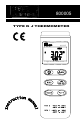
302 800005 TYPE K J THERMOMETER 800005 Type K and J Therm om eter
= CONTENTS TITLE PAGE I. Introduction…………...…………………. 1 II. Specifications………………………….. 1 III. Symbol Definition and Button Location……………………………….… 3 IV. Operation Instructions…………….5 4.1 Power-Up………………………………....….. 5 4.2 Connection the Thermocouples………….… 5 4.3 selecting the Temperature Scale……….….. 5 4.4 selecting the Thermocouple Type.…………. 5 4.5 Data-Hold Operation…………………….….. 5 4.6 Timer Operation……………………………… 5 4.7 Relative Operation…………………………… 6 4.8 MAX/MIN/AVG Operation…………………… 6 4.
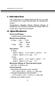
SPER800005-01 MAY.1999 I. Introduction: This instrument is a digital thermometer for use with any K-type and J-type thermocouple as temperature sensor. Temperature indication follows National Bureau of Standards and IEC584 temperature/voltage table for K-type and J-type thermocouples. II. Specifications: Numerical Display: 4 digital liquid crystal display Measurement Range: K-Type -200• ~ 1370• -328• ~ 2498• J-Type -200• ~ 760• -328• ~ 1400• Resolution: K-Type: -200°C~ 800°C 0.
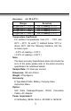
Accuracy: at ( 23 ± 5°C ) Range Accuracy K-Type -200°C ~ 1370°C J-Type -200°C ~ 760°C K-Type -328°F ~ 2498°F J-Type -328°F ~ 1400°F ±(0.1% reading + 0.7°C) ±(0.1% reading + 0.7°C) ±(0.1% reading + 1.4°F) ±(0.1% reading + 1.4°F) Temperature Coefficient: For ambient temperatures from 0°C ~ 18°C and 28°C ~ 50°C, for each °C ambient below 18°C or above 28°C add the following tolerance into the accuracy spec. 0.01% of reading + 0.03°C ( 0.01% of reading + 0.
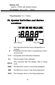
Battery Life: Approx. 100hrs with alkaline battery AC Adapter: 9VDC ±15% 100mA Plug Diameter: 3.5×1.35mm III. Symbol Definition and Button Location: Main Display H Timer Display : This indicates that the minus temperature is sensed. : It indicates that the timer is expressing in hours and minutes. °C °F : Centigrade and Fahrenheit indication. KJ HOLD : Thermocouple Type Indication : This indicates that the display data is being hold.
•REL : The reading is now under Relative Mode. : The Battery is not sufficient for proper operation.
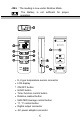
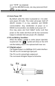
Tripod connector 1•2 Battery cabinet cover 1 •1 IV. Operation Instructions: 4.1 Power-Up Press the •I key to turn the thermometer On or OFF 4.2 Connection the Thermocouples For measurement, plug the thermocouple into the input connectors. 4.3 Selecting the Temperature Scale When the meter was first power on, the default scale setting is set at Celsius (°C) scale. The user may change it to Fahrenheit (°F) by pressing “ °C/°F ” button and vice versa to Celsius. 4.
When the counting exceed 59min 59sec, the time scale will be changed to hours and minutes and the “ H ” symbol will appear on the display. The counting can be reset by press and hold “ TIMER ” button for 2 sec. 4.7 Relative Operation: When one press the “•REL” button, the meter will memorize the present reading and the difference between the new reading and the memorized data will be shown on the display. Press the “•REL” button again to exit the Relative operation. 4.
and “ °C/°F ” are disabled. To exit the MAX/MIN mode, one may press and hold for two seconds. 4.9 Auto Power Off: By default, when the meter is powered on, it is under auto power off mode. The meter will power itself off after30 minutes if no key operation and RS232 communication. Key combination at power on or RS232 communication can disable auto power off. One may press and hold “HOLD” button and then power on the meter and there will be two successive beeps to indicate that auto power off is disabled.
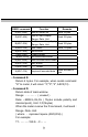
RS232 command Function K(ASC 4BH) S(ASH 53H) H(ASC 48H) T(ASC 54H) M(ASC 4DH) N(ASC 4EH) R(ASC 52H) C(ASC 43H) Ask for model No. Ask for main display Range, Data, Unit Ask for secondary display Range, Data, Unit Ask Status Hold button TIMER button AVG/MAX/MIN button Exit AVG/MAX/MIN mode REL button •/• button A(ASC 41H) Inquire all encoded data D(ASC 44H) B(ASC 42H) Remarks Send 4 bytes Send 22 bytes Send 22 bytes Send 13 bytes Send encoded 8 byte •Command K: Return 4 bytes.
(0x13) represent T1,- 199.9°C, The total byte number should be 7+1+7+1+5+chr(13)=22Bytes Command B: Return the counting of timer. •Command S: Return the operation mode HOLD•MAX•REL, if the mode is not entered, the related characters will be left as space. For example: when the meter is under MAX display, the meter will return: •••••MAX•••• •Command T: Equivalent to one pushing on the HOLD button. •Command M: Equivalent to one pushing on the HOLD AVG/MAX/ MIN button and no message is returned.
0 0 1 1 0 1 0 1 1 0 0 1 •MAXIMUN mode •MINIMUN mode •AVG mode •calculate MAX/MIN/AVG in back- ground and lcd "MAX""AVG""MIN" will flash. bit3: 1•0->K TYPE ,1•J TYPE(300 only has K type) bit4: 1•REL bit5: 1•HOLD, 0•not HOLD bit6: 1•LOW BATTERY , 0•BATTERY NORMAL bit7: 1•• 0•• 3th BYTE: bit7 bit6 bit5 bit4 bit3 bit2 bit1 bit0 no use no use no use Time no use X1_ minus OL unit X10 bit0: 1•main window value is OL, 0•not OL bit1: 1•main window value is minus, 0•main window value is plus.
6th BYTE: first two BCD code of sub window value. 7th BYTE: last two BCD code of sub window value.