VIBRATION METER 840063 Instruction Manual SPER SCIENTIFIC LTD.
CONTENTS Title Page I. Introduction .................................................................. 2 II. Panel Description ......................................................... 3 III. Operating Instructions A. General Measurement Procedures ......................... 3~4 B. Peak ........................................................................ 5 C. Data Hold ................................................................ 5 D. Datra Record .......................................
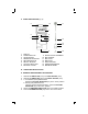
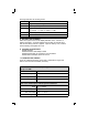
II. PANEL DESCRIPTION (fig. A) 10 9 11 1 4 3 7 6 2 5 12 13 14 8 1. 2. 3. 4. 5. 6. 7. 8. DISPLAY POWER BUTTON HOLD BUTTON RMS/PEAK SELECTOR RECORD BUTTON RECALL BUTTON ACC/VEL SELECTOR BATTERY COVER 9. 10. 11. 12. 13. 14. 15. 15 RS232 OUTPUT TERMINAL BNC SOCKET BNC PLUG MINI PLUG INPUT SOCKET VIBRATION SENSOR MAGNETIC BASE III. OPERATING INSTRUCTIONS A. GENERAL MEASUREMENT PROCEDURES 1. Attached the BNC PLUG (A11) to the BNC SOCKET (A10). 2. Attached the MINI PLUG (A12) to the INPUT SOCKET (A13).
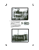
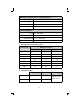
6 a. If the surface material of the object you are testing is a non-magnetic material, hold the VIBRATION SENSOR and touch the tip to the object (above). b.If the surface material is magnetic, connect the VIBRATION SENSOR to the MAGNETIC BASE (left) and touch it to the object's surface (below).
B. PEAK VALUE Switch the RMS/PEAK SELECTOR (A4) to the "PEAK" position. Peak value = 1.414 RMS value. C. DATA HOLD 1. Press the HOLD BUTTON (A3) during measurement to freeze the displayed value. "D.H" is shown on the LCD. 2. Press the HOLD BUTTON (A3) a second time to resume measurement. D. DATA RECORD (Displays the Maximum and Minimum readings.) 1. To start the Data Record function, press the RECORD BUTTON (A5) once. The LCD display will indicate "REC." 2.
Each digit indicates the following status: DO D1 to D4 D5 to D8 D9 End Word Upper Display reading, D1=LSD, D4=MSD All "?" (?, ?, ?, ?) Decimal Point(DP), position from right to the left 0 = No DP, 1 = 1 DP, 2 = 2 DP, 3 = 3 DP D10 to D14 All Zeros (0, 0, 0, 0, 0) D15 Start Word RS232 FORMAT: 9600, N, 8, 1 G. BATTERY REPLACEMENT When the top left corner of LCD display indicates "LBT," it is time to replace the battery. Accurate readings may be taken for several hours after the low battery indicator appears.
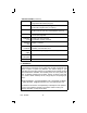
GROUP G: Large machines on heavy foundations. Good 0 ~ 1.80 mm/s Acceptable 1.81 ~ 4.50 mm/s Still permissible 4.51 ~ 11.2 mm/s Dangerous > 11.2 mm/s GROUP T: Largest machines and turbo machines with special foundations. Good 0 ~ 2.80 mm/s Acceptable 2.81 ~ 7.10 mm/s Still permissible 7.11 ~ 18.0 mm/s Dangerous > 18 mm/s J. ISO 2954 Sensitivity Relative Table Frequency Hz Relative sensitivity Normal Value Minimum Value Maximum Value 10 1.0 0.8 1.1 20 1.0 0.9 1.1 40 1.0 0.9 1.
SPECIFICATIONS (continued) Frequency Weight Dimension Display Calibration Point Sampling time Operating conditions Power supply Power consumption Circuit 10 Hz~ 1 KHz, sensitivity relative during the frequency range meets ISO 2954 (see pg 6). Meter with battery: 10 oz (230 g). Probe with magnetic base: 2 oz (50 g). Meter: 17" × 3" × 1 ½" (80 × 75 × 35 mm) Probe cord: 49" (125 cm), probe diameter: (19 mm) 61 mm x 34 mm super large LCD display. 15 mm (0.6") digit size.