Datalogging CFM Anemometer 840001 Instruction Manual SPER SCIENTIFIC LTD.
TABLE OF CONTENTS 1. INTRODUCTION ............................................................................ 3 2. PANEL DESCRIPTION................................................................... 4-5 3. MEASURING PROCEDURES ........................................................ 5 3-A Air Velocity and Ambient Temp. Measurement ....................... 5 3-B Air Flow Measurement (CMM/CMF)........................................ 5 3-C Type K/J (Thermocouple) Thermometer .................................
1. INTRODUCTION Automatically records up to 16,000 (!) data points in the field along with time and date. These can later be downloaded to a computer via the meter’s RS232 port and the results viewed instantly on software which comes with the unit. The software also enables real time data logging directly from the meter to the computer.
2.
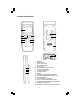
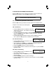
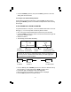
19 21 20 19 VANE 20 PROBE HANDLE 21 PROBE PLUG 3. MEASURING PROCEDURES See "Advanced Adjustment Procedures" (pg 7) to set the default temperature scale (°C or °F), air velocity unit, (m/S, Ft/min, Km/h, Knots or Mile/h), air flow measurement (CMM or CMF), and area size (Meter^2 or Ft^2). 3-A. Air Velocity and Ambient Temperature Measurement • Insert the PROBE PLUG (21) into the PROBE INPUT SOCKET (17). • Slide the PROBE LOCK SWITCH (18) to the ◄LOCK position.
3-D. Data Hold • While measuring, press the HOLD (3) button to freeze the displayed value. • "HOLD" and the measurement are displayed. • Press the HOLD (3) button again to exit. 3-E. Maximum / Minimum To record the maximum and minimum readings: • Press the REC (4) button once. "REC" appears on the LCD. • Press the REC (4) button again. "MAX", "REC" and the maximum measurement appear on the LCD. • Press the REC (4) button again. "REC Min" and the minimum measurement appear on the LCD.
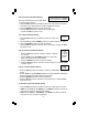
4. ADVANCED AJUSTMENT PROCEDURES Press the SET button (8) for at least two seconds to enter the advanced adjustment procedures. Press the ESC (3) button to exit. Before executing the advanced adjustment procedures, exit the HOLD and RECORD functions. 4-A. Check Remaining Available of Data Points Press the SET button (8) at least 2 seconds until the lower display shows: "XXXXX" is the number of free data points. XXXXX Memory Space 4-B.
4-E. Auto Power Off Default Setting 1 = Auto Power Off - Enabled 0 = Auto Power Off - Disabled The meter will automatic shut off after about 10 minutes without activity. • Press the SET (8) button as needed to reach the "auto power off" screen. • Use the ▲ (5) or ▼ (6) buttons to enable / disable this feature. • Press the ENTER (4) button to save the settings. • Press the SET (8) button to advance to the next option, or press the ESC (3) button to exit. 4-F.
• Press the ENTER (4) button, then press the ESC (3) button to save the setting and exit this function. 4-J. Escape from Advanced Adjustments For the above procedures (B through F), press the ESC (3) button before pressing the ENTER (4) button to exit advanced adjustments without saving the changes. 5. UPLOADING DATA FROM THE METER To upload the data to a computer, connect the RS232 cable and run the software (pg 11). You can only send one memory block at a time.
6. RS232 PC SERIAL INTERFACE The instrument features a 3.5 mm RS232 OUTPUT TERMINAL (14). The signal output is a 16-digit data stream that can be adapted to user-defined applications. A RS232 lead with the following connection is required to link the instrument with the PC serial interface. Meter (3.5 mm jack plug) PC (9W ‘D” Connector) Center Pin .................................. Pin 4 Ground/shield ............................ Pin 2 Pin 2 Pin 5 2.
8. TROUBLESHOOTING • To reset the system, slide the PROBE LOCK SWITCH (18) between the "On" and "Off" positions once or twice. • Or, gently insert a pin or small object into the SYSTEM RESET (13) while turning on the meter. 9. OPTIONAL ACCESSORIES 840090 840092 840093 840094 840097 Type K Water Resistant Instrument Pouch Bench-Top Tripod Field Tripod USB RS232 Serial Adapter AC to DC 9V Adapter and Type J Probes 10. SOFTWARE The software CDs feature auto-installation.
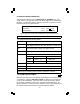
Thermocouple Range Res. Accuracy -58~2372ºF ±(0.2% + 1ºF) Type K -50~1300ºC ±(0.2% + 0.5ºC) 0.1º -58~2012ºF ±(0.2% + 1.8ºF) Type J -100~1100ºC ±(0.2% + 1ºC ) Type K/J specification tests under the environment RF Field Strength less than 3 V/M and frequency less than 30 MHz. Temp. Compensation Automatic for K/J thermometers. Misc. Operating Conditions Display Sampling Time Power Drain Dimensions Weight: 0 to 50°C, Less than 80% RH. Approximately 1 second. Approximately DC 21.5 mA for the meter. DC 27.