
Safety Information


1) FEATURES:
• UL Listed to both US and Canadian Standards
• One Year Limited Warranty
• Locates AC Breakers or Fuses
• No need to interrupt power
• Distinctive signal
• Audible and visual indication
• Does not interfere with sensitive electronic equipment
1. Self-calibrating receiver with audible and visual indicators.
2. Self-powered transmitter with audible and visual indicators.
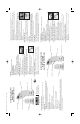
2) PREPARATION FOR USE (figure 1):
1. Install a 9-volt alkaline battery (battery not included).
2. Reinstall battery cover.
3. Test battery by turning on unit (rocker switch)
4. L.E.D. will light brightly indicating the battery is in good condition.
3) TESTING THE TRANSMITTER AND RECEIVER (figure 2):
1. Plug the transmitter into a powered electrical wall outlet.
2. L.E.D will flash and beeper will sound at approximately seven times per second.
3. Turn on receiver and place target on the tip against rear of transmitter (as shown).
4. Receiver L.E.D. will flash and beeper will sound in time with the
transmitter.
5. While continuing to hold receiver against rear of transmitter press
and hold calibration switch.
6. The receiver will stop responding with-in one to two seconds.
7. Release calibration switch, receiver will again respond
to the transmitter’s signal.
8. This completes the test; turn off the receiver to reset the calibration circuit to full sensitivity.
4) LOCATING A CIRCUIT BREAKER (figure 3):
1. With the transmitter plugged into an AC outlet go to the circuit breaker panel and open
the cover.
2. Turn on the receiver and place target on the tip firmly against the first circuit breaker in
the panel.
3. Press and hold the calibration switch while moving the receiver across the circuit breakers.
4. When the receiver responds to a circuit breaker stop movement until the receiver stops
responding, then continue moving the receiver to the next breaker.
5. During the calibration process the receiver may respond to more than one of the circuit
breakers in the panel, each time this occurs wait for the receiver to stop responding before
moving to the next circuit breaker.
6. After scanning all the circuit breakers in the panel release the calibration switch and rescan
the circuit breakers.
7. Only one breaker will now produce a response in the receiver.
8. While continuing to hold the receiver against this breaker turn off the breaker, this will
remove power to the remote transmitter and the receiver will cease producing a response.
This confirms that the transmitter is no longer receiving power.
9. Turn off receiver; additionally this resets the calibration circuit if
another scan is desired.
10. Always confirm that power to the outlet has been removed by
noting the absence of sound and light when in the presence of
the transmitter.
11. Unplug transmitter when not in use.
5) OVERHEAD LIGHTING:
The circuit breakers controlling ceiling lights may also be identified
by using a light socket adapter or socket to clip lead adapter such
as the
Sperry CS61200AS Adapter Set (sold separately) as shown
in figure 4.
6) SAFETY NOTE:
Since the routing of electrical wiring in the home can take many forms, it is possible for
additional hot wires controlled by different circuit breakers to be present in the outlet box.
Because of this possibility, it is recommended that an
AC Voltage Sensor such as the
Sperry Model VD6504
(sold separately) be used to test for the presence of additional hot
wires in the outlet box prior to performing any work inside the box.
7) LIGHT DIMMERS:
High power light dimmers may interfere with the operation of the unit by giving a false
response when scanning the circuit breaker panel. The presence of such a light dimmer will
produce a much higher flash and beep rate from the receiver compared to the normal rate of
seven times per second. It is recommended that any dimmers in operation be set to full
power, or shut off when using the Circuit Breaker Finder.
8) SWITCH CONTROLLED OUTLETS:
Because wall switches are sometimes used to control outlets, be sure to turn on these
switches prior to plugging in the transmitter.
9) BATTERY LIFE:
While powered, the receiver will consume 10ma from the battery. The L.E.D. in the receiver
will rapidly become dim when the battery voltage drops below 8 volts and will completely
extinguish at 7.5 volts. Replace the battery when the L.E.D. fails to light or becomes
noticeably dim. Turn off receiver when not in use to prolong battery life.
10) SPECIFICATIONS:
Working Voltage Range 80-140V max. to ground
Frequency: 50-60Hz
Operating Temperature: 32 to 122F(0-50C)
Storage Temperature: -4 to 158F(-20-70C)
Power Supply:
Receiver: One (1) 9V Transistor Type Battery (NEDA #1604) Part # B-4
Dimensions:
Transmitter: 3.3”
H x 2.6”W x 1.1” D (83 x 67 x 28mm)
Receiver: 6.3”
H x 3.4” W x 1.1” D (159 x 86 x32mm)
Weight:
Transmitter: 2.5 oz. (70g)
Receiver: 5.1 oz. (145g)
1 YEAR WARRANTY
limited solely to repair or replacement; no warranty of merchantability
or fitness for a particular purpose. Product is warrantied to be free of defects in materials and
workmanship for the normal life of the product. In no event shall Sperry Instruments be liable
for incidental or consequential damage.
INSTRUCCIONES DE OPERACIÓN
Modelo CS550A
BUSCADOR DE INTERRUPTORES
FIG. 1
FIG. 2
FIG. 3
FIG. 4
1) CARACTERÍSTICAS:
• Registrado en UL tanto con las normas de EE.UU. como las de Canadá
• Garantía limitada de un año
• Localiza interruptores o fusibles de CA
• No es necesario cortar la electricidad
• Señal distintiva
• Indicación auditiva y visual
• No interfiere con equipos electrónicos sensibles
1. Receptor autocalibrado con indicadores auditivos y visuales.
2. Transmisor autónomo con indicadores auditivos y visuales.
2) PREPARACIÓN PARA EL USO (figura 1):
1. Instale una batería alcalina de 9 voltios (no se incluye).
2. Vuelva a colocar la cubierta de la batería.
3. Pruebe la batería encendiendo la unidad (interruptor basculante)
4. El LED se iluminará indicando que la batería está en buenas condiciones.
3) PRUEBA DEL TRANSMISOR Y EL RECEPTOR (figura 2):
1. Enchufe el transmisor en un tomacorriente energizado.
2. El LED destellará y sonará una alerta sonora a
aproximadamente siete veces por segundo.
3. Encienda el receptor y coloque el objetivo en la punta
contra la parte trasera del transmisor (como se muestra).
4. El LED del receptor destellará y la alerta sonora sonará sincronizada con el transmisor.
5. Mientras sostiene el receptor contra la parte trasera del
transmisor, presione y sostenga el interruptor de calibración.
6. El receptor dejará de responder en uno o dos segundos.
7. Suelte el interruptor de calibración; el receptor responderá nuevamente a la señal del
transmisor.
8. Esta acción da por terminada la prueba; apague el receptor para restablecer la
sensibilidad completa en el circuito de calibración.
4) LOCALIZACIÓN DE UN INTERRUPTOR (figura 3):
1. Con el transmisor enchufado en un tomacorriente de CA, vaya al panel de interruptores y
abra la cubierta.
2. Encienda el receptor y coloque el objetivo sobre la punta firmemente contra el primer
interruptor del panel.
FIG. 1
FIG. 2
OPERATING INSTRUCTIONS
Model CS550A
CIRCUIT BREAKER FINDER
Milwaukee, WI 53209
Phone: 1-800-645-5398
www.sperryinstruments.com
Interruptor basculante
Receptor
Compartimiento de batería
Transmisor
Punta sensora (objetivo)
Interruptor de calibración
Rocker Switch
Receiver
Battery Compartment
Transmitter
Sensing Tip (Target)
Calibration Switch
CS550A_IM_0807 9/13/07 8:31 AM Page 1