Instruction Manual
EN NOTICE All instructions, warranties and other collateral documents are subject to change at the sole discretion of Horizon Hobby, Inc. For up-to-date product literature, visit horizonhobby.com and click on the support tab for this product.
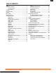
EN TABLE OF CONTENTS DSMX..........................................................................4 Transmitter Functions Charging Batteries...............................................6 Install Batteries....................................................6 Binding........................................................................7 Using transmitter.........................................................8 Antenna.......................................................................8 Main Screen..
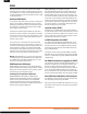
EN DSMX Spektrum launched the 2.4GHz RC revolution with its DSM2 technology. Since then millions of hobbyists the world over have come to embrace 2.4 as the way to fly. Spektrum leads the way yet again with DSMX; the world’s first wideband, frequency-agile 2.4GHz signal protocol. How Does DSMX Work? It’s a crowded 2.4GHz world out there and every 2.4GHz system faces the same challenges.
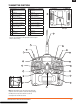
EN TRANSMITTER FUNCTIONS Press Function A Antenna B Throttle Cut Function K Charge Port L Rudder Trim C Mix/Throttle Hold (Mode 2) Trainer/Bind (Mode 1) M Throttle Trim (Mode 2) Elevator Trim (Mode 1) D Rudder Dual Rate (Mode 2) Gear/Flight Mode (Mode 1) N Throttle/Rudder Stick (Mode 2) Elevator/Rudder Stick (Mode 1) E Aileron Dual Rate O Elevator Dual Rate F Aileron/Elevator Stick (Mode 2) Aileron/Throttle Stick (Mode 1) P Gear/Flight Mode (Mode 2) Rudder Dual Rate (Mode 1) G El
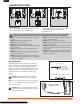
EN TRANSMITTER BATTERIES 1. 2. Install Batteries This transmitter requires 4 AA batteries. Transmitters are sold with and without batteries and a Spektrum charger. 3. 1. Remove battery cover from the back of the transmitter. 2. Install batteries as shown where batteries fit. 3. Install battery cover.
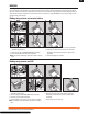
EN BINDING You must bind the receiver to the transmitter before it will operate. Binding is sharing identification codes between the receiver and the active memory of the transmitter. Once bound, the receiver only connects to the transmitter when the previously bound model memory is selected. You will need to rebind after the model is set in the transmitter to fully program the model’s failsafe positions. If another model memory is selected, the receiver will not connect.
EN USING TRANSMITTER Antenna The transmitter antenna bends and turns at the hinge (A) and only bends and turns to the front of the transmitter. The antenna cannot point to the back of the transmitter. Turn antenna tip to point away from the model and ground. Signals transmit strongest from the antenna shaft, not the tip. WARNING: Do not pick up the transmitter by the antenna. Do not alter or put weight on the antenna.
EN PROGRAMMING GUIDE This manual describes airplane and helicopter software functions. Some functions enable other functions. For example within Model Type in the Setup list, you can choose between Model Type ACRO and Model Type HELI. These then enable the programming functions that follow Model Type according to the model type you choose.
EN FUNCTION OPTIONS NOT SHARED BY THE MODEL TYPES Acro Inhibit Activate MODEL TYPE REVERSE THRO-N ELEV-N GEAR-N DUALAILE List AILE-N RUDD-N FLAP-N DUALAILE WING TAIL MIX TRAVEL ADJ DIFFERNTIAL DIFFERNTIAL List 0% THRO ELEV GEAR 0 0 0 List AILE RUDD FLAP 0 0 0 FLAPS List THRO 100% AILE 100% ELEV 100% RUDD 100% GEAR 100% FLAP 100% DUALAILE RATE SUB TRIM MIX 1 List DIFFRNTIAL INHIBIT MIX 2 Heli MODEL TYPE REVERSE THRO-N ELEV-N GYRO-N CCPM 120° List GYRO AILE-N RUDD-N PITC-N GY
EN MODEL TYPE This transmitter supports 2 model types: Airplane (ACRO) and Helicopter (HELI). Model Type is stored in a model memory. MODEL TYPE MUSTANG MDL6 5.0V List DN06:00 CAUTION: When Model Type is changed, programming for a model memory is erased and returned to factory default settings. A Options affecting other screens and Functions ACRO HELI A MODEL NAME A Model Name function assigns a name to a specific MDL6 MUSTANG memory, so the model memory is easier to identify. 5.
EN WING TAIL MIX Wing Tail Mix function supports Normal, Dual Aileron, V-Tail and Elevon (Delta) mixing. Refer to your model’s manual for recommended settings. See Appendix for information about recommended wing type servo installations on scratch built models. Normal This normal or default setting for airplanes is 1 servo channel for aileron, 1 channel for elevator and 1 channel for the rudder. These common wing and tail functions are enabled when you set DUALAILE, ELEVON and V-TAIL at INH (inhibit).
EN TIMER B The Timer function includes a timer on the Main MDL6 MUSTANG screen and an audible alarm. When the time List TIMER 5.0V DN06:00 expires, 5 beeps sound every 5 seconds. C A Timer DOWN – This sets a countdown (from up MDL6 MUSTANG DOWN TIMER-06:00 to 59 minutes and 50 seconds). SWITCH---TRAINER Timer UP – This sets a count-up timer (up to 59 minutes and 50 seconds). The start time is programmable. The default start of D 00:00 is recommended.
EN CONTRAST CONTRAST A The Contrast function adjusts the image on the LCD for visibility in sunlight. The default value is 50%. A Option value (0-100%) 50% COPY/RESET The Copy/Reset function supports copying the active model memory A to any of the other 9 available model memories. This is useful for setting up a model with different programming or to set up a similar model.
EN TRAVEL ADJ (Travel Adjust) The Travel Adj function supports precise endpoint adjustments in each direction for each of the 6 channels, independently. The travel adjust range is from 0–125%. Available channels depend on the Model Type of the active model memory. A Channels B Optional values C FLAP on ACRO type and PITC on HELI type D Arrows change direction by changing control stick or switch positions.
EN THRO CUR (Throttle Curve) The Thro Cur function supports setting values for 5 positions in the throttle response curve of 3 different modes: NORM (Normal), STUNT and HOLD. Note: In TH. HOLD, throttle curve is a flat line representing a hold condition. You can adjust this at the 5 positions (L, 2, 3, 4 and H). The throttle trim switch is only active when the flight mode switch is in the NORM (0) position.
EN SWASH MIX The Swash Mix function supports adjusting mix among the CCPM swashplate servos, AILE (aileron), ELEV (elevator) and PITC (pitch). Refer to your model’s manual for recommended settings. A Input B Input values (-125 to +125%). (For example, when the swashplate moves up when the control stick is moved down and the channel’s swash mix value is positive, make the channel’s value negative to make the swashplate move down with the same stick movement.
EN DIFFERENTIAL The Differential function decreases the amount an aileron moves down without affecting the amount the other aileron moves up. This can decrease swerving (adverse yaw) tendencies during roll maneuvers. Differential is not available in this transmitter for flying-wing airplanes (ELEVON option in WING TAIL MIX). Note: Use of the Differential function requires choosing DUALAILE in WING TAIL MIX function. DIFFERNTIAL DUALAILE RATE Adjust for middle-to-high throttle settings: 1.
EN FAILSAFE When you bind your transmitter to a Spektrum receiver, you program the receiver with Failsafe defaults. If the receiver loses connection to the transmitter, the receiver goes to Failsafe, operating in default control positions programmed at binding (until connection is restored to the transmitter). NOTICE: Failsafe varies among receivers. Before using a receiver, read receiver’s instructions for Failsafe instructions and information.
EN In airplanes, install the main receiver in the servo tray in the center of the fuselage. Install the remote receiver in the servo tray by the side of the fuselage or in the turtle deck (space behind the canopy and in front of the vertical stabilizer). In helicopters, install receivers in the servo tray, where there is usually sufficient room for receiver separation. Where there is not sufficient room, install a receiver on an external receiver mount made of clear plastic.
EN TROUBLESHOOTING GUIDE Problem Possible Cause Solution Transmitter and receiver are too near each other. Move transmitter 8 to 12 feet (2.4 to 3.6m) from receiver Throttle channel is reversed Move away from large metal objects (vehicles, etc.
EN FCC INFORMATION This device complies with part 15 of the FCC rules. Operation is subject to the following two conditions: (1) This device may not cause harmful interference, and (2) this device must accept any interference received, including interference that may cause undesired operation. CAUTION: Changes or modifications not expressly approved by the party responsible for compliance could void the user’s authority to operate the equipment.
EN WARRANTY AND REPAIR POLICY Warranty Period Exclusive Warranty- Horizon Hobby, Inc., (Horizon) warranties that the Products purchased (the “Product”) will be free from defects in materials and workmanship for a period of 1 year from the date of purchase by the Purchaser. 1 Year Limited Warranty Horizon reserves the right to change or modify this warranty without notice and disclaims all other warranties, express or implied.
EN WARRANTY AND SERVICE CONTACT INFORMATION Country of Purchase Horizon Hobby Address Phone Number / Email Address Horizon Service Center (Electronics and engines) 4105 Fieldstone Rd Champaign, Illinois, 61822 USA 877-504-0233 Online Repair Request: visit www.horizonhobby.com/repairs Horizon Product Support (All other products) 4105 Fieldstone Rd Champaign, Illinois, 61822 USA 877-504-0233 productsupport@horizonhobby.
EN APPENDIX Control Stick Length Adjustment 1. Adjust control stick length using a 1.5mm Allen wrench. 2. Turn the setscrew in the stick counterclockwise to loosen it. Make stick shorter by turning it clockwise or longer by turning it counterclockwise. 3. After adjustment of stick length, tighten setscrew. Control Stick Tension Adjustment 1. Remove batteries from transmitter. 2. Remove 6 screws from transmitter back cover using a #1 Phillips screwdriver. 3. Carefully remove transmitter’s back cover.
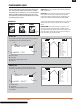
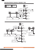
EN RECOMMENDED SERVO CONNECTIONS Dual Aileron Wing Type Connection A V-Tail Type Connection B C A AUX1 servo port (left aileron) B AILE servo port (right aileron) Elevon Wing Type Connection E Servo Control D C ELEV servo port (left V-tail) D RUDD servo port (right V-tail) F E AILE servo port (left aileron) F ELEV servo port (right aileron) For a delta wing or elevon wing setting, check the control throw directions. Begin by checking the aileron direction.