
Users Manual Part 2

33
HDE 11/2018 732.29.128
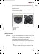
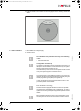
The WT 210 has a sabotage sensor which triggers the integrated acoustic signal
generator and activates the alarm relay if the reader is removed from the mounting
frame
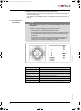
All locking procedures and any removal of the device from the frame are logged in
the memory of the WT 210.
The WT 210 has a radio interface, via which the terminal can be configured and audit
trails read out with the aid of the MDU.
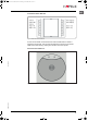
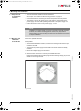
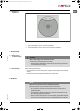
WT 210 wall terminal
Fig. 2: WT 210 for flush mounting
5. Description of functions
5.1 Function of the
access control
system
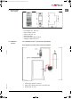
The access control system consists of the WT 210 wall terminal with an external
power supply and a connected electrical or electro-mechanical opening device and
the configuration software.
The settings of the WT 210 which are made in the configuration software are
transmitted to the WT 210 by the MDU 110 mobile data transfer unit.
Audit trails are also read out of the WT 210 by the MDU 110 so that they can be
loaded into the software of the administrator PC and processed.
Other components such a door release button can also be connected to the WT 210.
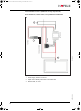
Amongst other things, the following installation versions are possible:
Installation version 1 (low security requirements)
• A door with a WT 210, electric opening device and internal door opener push
button.
See chapter "5.4.1 Installation version 1 (low security requirements)" on page
35.
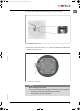
1Front view
2Rear view
1
2
ins-src-732.29.128.book Seite 33 Dienstag, 20. November 2018 10:27 10