
Users Manual Part 2

HDE 11/2018 732.29.128
38
6. Mounting and installation
6.1 Requirements
for installation
locations
• The environmental conditions must be adhered to.
See chapter "10.2 Ambient conditions during operation" on page 42.
• Connection leads for connecting the various components must be present.
• The voltage of the on site power supply must meet the requirements of the
power supply unit used. See operating instructions of the power supply unit.
• Lead cross-section of the on site power supply: 1.5 mm
6.2 Mounting and
installation
of the WT 210
Personnel: qualified electrician
Prerequisites:
• At the desired installation location, a switch box according to DIN 49073 is pre-
installed in the wall.
• The lead for the power supply and the lead to the electric strike are already
installed.
1. Disconnect voltage supply from the mains.
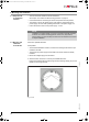
2. Screw the frame of the WT 210 to the pre-installed switch box.
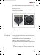
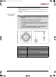
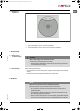
Ensure that the black mark is at the top right and the retaining rails (fig. 9/1) for the
reader are on the right and left.
Fig. 9: Frame
NOTE
Installation on metal surfaces (e.g. doors or panels) is generally possible.
However, the metal surroundings (doors, frames, etc.) may have an
adverse effect on the functionality of the terminal. We therefore recommend
a sample installation.
ins-src-732.29.128.book Seite 38 Dienstag, 20. November 2018 10:27 10