Spicer Tandem Drive Axles ® Service Manual Spicer® Tandem Drive Axles AXSM-8661 September 2007
TABLE OF CONTENTS Identification Axle .............................................................................. 1 Model Numbering System ........................................... 2 Gear Set ........................................................................ 2 Axle Lubricant Recommendations .......................................... 3 General Precautions ................................................................ 4 Components Power Divider ....................................................
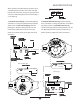
AXLE IDENTIFICATION All axle assemblies are identified with two tags. One located on the differential carrier, and the other located on the right hand side of the axle housing. Two types of tags may be found on the axle, an aluminum tag that is riveted on the assembly or a coated mylar tag. JULIAN D ATE CODE DA 97 1 70 17 MODEL YEAR The aluminum axle assembly tag contains the following items: serial number, according to the julian date, Dana part number, and the model.
MODEL IDENTIFICATION NUMBERING SYSTEM Family (J,W) J 400 S N Load Carrying Capacity (340 = 34,000 Lbs.) (380 = 38,000 Lbs.) (400 = 40,000 Lbs.) (440 = 44,000 Lbs.) (460 = 46,000 Lbs.) Options (N= No-SPIN® option) Gearing Type (S= Single Reduction) * No-SPIN® is a registered trademark of Tractech GEAR SET IDENTIFICATION Manufacturer's Date- Date gear set was made. PINION ETCH SPICER TRADEMARK Spicer Trademark- Dana Diamond and location of manufacturing facility. +15 047GP000- Part number of pinion.
AXLE LUBRICANT RECOMMENDATIONS To ensure proper lubrication and operating temperature, correct lubricants and lubricant levels must be obtained. SUBMERSION OR DEEP WATER FORDING In the event the axle assembly should become submerged in water, particularly if over the vent or breather, it is recommended that the lubricant be drained and all parts be inspected for water damage and/or contamination. Reassemble the carrier to the housing and refill with specifed gear lubricant.
GENERAL PRECAUTIONS IMPORTANT READ THIS SECTION BEFORE STARTING ANY SERVICE PROCEDURES GENERAL AXLE DESCRIPTION This manual covers maintenance and rebuild procedures for the Spicer J340-S, J380-S, J400-S, W440-S and W460-S rear drive tandem axle assemblies. Accordingly, anyone who uses a service procedure or tool different than shown must insure that their safety, and the vehicle's safety, will not be jeopardized by the service method selected.
POWER DIVIDER COMPONENTS Idler Gear Shaft Idler Gear Front Bearing Cone IMPORTANT: Torque specifications, shown on illustration, apply only to J Model. See Page 3334 for W Model torque specifications.
FORWARD REAR AXLE COMPONENTS Flanged Hex Nut (500-600 Lb-Ft) (680-816 N-m) Output Yoke Assembly IMPORTANT: Torque specifications, shown on illustration, apply only to J Model. See Page 3334 for W Model torque specifications.
REAR REAR AXLE COMPONENTS IMPORTANT: Torque specifications, shown on illustration, apply only to J Model. See Page 3334 for W Model torque specifications.
REMOVAL OF DIFFERENTIAL CARRIER FROM AXLE HOUSING FORWARD REAR CARRIER (WITH POWER DIVIDER) Threaded RemovalHole NOTE: Steam clean axle assembly. 1 . Block wheels. 2 . Remove axle housing drain plug and drain lubricant. 3 . Disconnect drive shafts from input and output shaft end yokes. Threaded RemovalHole NOTE: If end yoke and/or seal is to be replaced, loosen flanged hex nut at this time. Figur iguree 1 4 . Remove axle shaft flange nuts.
REMOVAL OF DIFFERENTIAL CARRIER FROM AXLE HOUSING 7. Support the differential carrier assembly on a roller jack. Secure as necessary to prevent it from falling off the jack when removed from the housing. 10 . Remove carrier assembly from under the vehicle. 11 . Mount carrier assembly in a suitable rebuild stand. (Refer to Recommended Service Tools, Pgs. 35-36) 8. Use a breaker bar to loosen the differential carrierto-housing mounting bolts. Remove all bolts except top two.
DIFFERENTIAL DISASSEMBLY Oil Scoop Bolt (7-9Lb-Ft) (9-12 N-m) Oil Scoop IMPORTANT: Torque specifications, shown on illustration, apply only to J Model. See Page 3334 for W Model torque specifications.
DIFFERENTIAL DISASSEMBLY IMPORTANT: If any gears are to be replaced, they must be replaced in sets. Inspect thrust washers for scoring and excessive wear. Replace all worn or damaged parts. 8 . Next, use a round type punch to drive out the remaining portion of the rivet. 7. When it is necessary to remove ring gear from differential case, carefully center punch each rivet head. Use a 9/16" drill bit on the J model carrier rivets and a 11/16” drill bit for the W model carrier rivets.
INTER-AXLE DIFFERENTIAL DISASSEMBLY Spiral Snap Ring Inter-Axle Differential Rear Bearing Inter-Axle Differential Case Assembly Fill Plug Inter-Axle Differential Cover Input Bearing Cone Input Bearing Cup Pinion Oil Seal Shim (Selective) End Yoke Assembly Inter-Axle Differential Cover Bolt (75-90 Lb-Ft) (102-122N-m) Flanged Hex Nut (900-1,200 Lb-Ft) (1,220-1,627N-m) 1 . Remove the inter-axle shift cylinder assembly, compress spring and remove retainer clip. Remove spring. 2 .
INTERMEDIATE CASE DISASSEMBLY Idler Gear Shaft Idler Gear Front Bearing Cone IMPORTANT: Torque specifications, shown on illustration, apply only to J Model. See Page 3334 for W Model torque specifications.
PINION DISASSEMBLY Carrier Housing IMPORTANT: Torque specifications, shown on illustration, apply only to J Model. See Page 3334 for W Model torque specifications.
OUTPUT SHAFT DISASSEMBLY Flanged Hex Nut (500-600 Lb-Ft) (678-813 N-m) IMPORTANT: Torque specifications, shown on illustration, apply only to J Model. See Page 3334 for W Model torque specifications. End Yoke Assembly (Output) Output Shaft Oil Seal Output Shaft Bearing Cage Bolt (30-40 Lb-Ft) (41-55 N-m) Output Shaft Bearing Snap Ring Output Shaft 1 . Remove rear drive shaft. 6 . Remove bearing and retainer from shaft. 2 . Remove output shaft bearing cage assembly from forward rear axle housing. 7.
CLEANING AND INSPECTION CLEANING GEARS 1. Parts should be cleaned with emulsion cleaners or petroleum base cleaning solvent. NOTE: Alkaline type solutions may cause damage to machined surfaces and should be avoided. 2 . Make sure interior of axle housing is clean prior to reassembly. 3 . Clean all gasket surfaces of old material. DRYING Inspect gears for excessive wear or damage. Replace gears that are pitted, scored, broken, or worn.
PINION ASSEMBLY Carrier Housing IMPORTANT: Torque specifications, shown on illustration, apply only to J Model. See Page 3334 for W Model torque specifications.
PINION ASSEMBLY does not align with slots in nut, tighten nut until they are aligned. Do not install roll pin at this time. CAUTION: Wash spacer thoroughly of emery cuttings before installing on pinion. On rear carriers, install end yoke onto pinion using yoke installer service tool, (See Figure 11 and Recommended Service Tools Pgs. 35-36), without seal to allow proper setting of bearing preload. Tighten pinion nut to 9001200 Lb-Ft (1,220-1,627 N-m). 14 .
PINION ASSEMBLY J Model Inches MM .720 18.29 .721 18.31 .722 18.34 .723 18.36 .724 18.39 .725 18.41 .726 18.44 .727 18.47 .728 18.49 .729 18.52 .730 18.54 .731 18.57 J Model Inches MM .732 18.60 .733 18.62 .734 18.64 .735 18.67 .736 18.69 .737 18.72 .738 18.75 .739 18.77 .740 18.80 .741 18.82 .742 18.85 .745 18.92 W Model Inches MM .895 22.73 .896 22.76 .897 22.78 .898 22.81 .899 22.84 .900 22.86 .901 22.89 .902 22.91 .903 22.94 .904 22.96 .905 22.99 .906 23.01 W Model Inches MM .907 23.04 .908 23.06 .
PINION POSITION and nicks prior to assembly or leaks will occur and pinion position can be affected. in thousandths of an inch (.001) to be added or subtracted from the nominal dimension for the best running position for that particular gear set. 7. Install pinion and pinion cage assembly into carrier. NOTE: Studs can be used to assist in alignment. EXAMPLE: 8 . Tighten pinion cage to carrier bolts. (See Torque Specifications Chart, Pgs.
PINION SETTING CHART 21
DIFFERENTIAL ASSEMBLY Oil Scoop Bolt (7-9Lb-Ft) (9-12 N-m) Oil Scoop IMPORTANT: Torque specifications, shown on illustration, apply only to J Model. See Page 3334 for W Model torque specifications.
DIFFERENTIAL INSTALLATION Oil Pick-Up Plate Figur 5 iguree 1 15 1 . Three differential cases are used with the W Model carriers, depending on the ratio. Two of the cases have two oil pick-up plates attached. Clean and coat bolts with Loctite #271 or its equivalent. Assemble and torque bolts to 7-9 Lb-Ft (9-12 N-m) 6 . Check ring gear and pinion backlash in four equally spaced positions around the ring gear with a dial indicator as shown. Acceptable backlash tolerance is .006"-.012". See Figure 16.
OUTPUT SHAFT ASSEMBLY Flanged Hex Nut (500-600 Lb-Ft) (678-813 N-m) End Yoke Assembly (Output) Output Shaft Oil Seal Output Shaft Bearing Cage Bolt (30-40 Lb-Ft) (41-55 N-m) Output Shaft Bearing Snap Ring Output Shaft 1 . Support output shaft bearing and press output shaft into bearing. 5 . Clean mating surface on axle housing and output shaft bearing retainer. Apply a 1/16” bead of Loctite #518 Gasket Eliminator on housing mounting flange and around bolt holes.
INTERMEDIATE CASE ASSEMBLY Idler Gear Shaft Idler Gear Front Bearing Cone IMPORTANT: Torque specifications, shown on illustration, apply only to J Model. See Page 3334 for W Model torque specifications.
INTERMEDIATE CASE ASSEMBLY 14 . Install shift fork shaft into intermediate case and thread into shift fork. Torque shaft to 30 to 38 Lb- Ft (41-52 Nm). Place spring over shaft. Compress spring and install retainer clip into groove in shaft. Intermediate case is now ready for assembly of inter-axle differential. spacer. Use a thinner spacer to decrease end play or a thicker spacer to increase end play. Any preload on the gear bearing will cause premature bearing failure. 11 .
INTER-AXLE DIFFERENTIAL ASSEMBLY Spiral Snap Ring Inter-Axle Differential Rear Bearing IMPORTANT: Torque specifications, shown on illustration, apply only to J Model. See Page 3334 for W Model torque specifications. Inter-Axle Differential Case Assembly Fill Plug Inter-Axle Differential Cover Input Bearing Cone Input Bearing Cup Pinion Oil Seal Shim (Selective) End Yoke Assembly Inter-Axle Differential Cover Bolt (75-90 Lb-Ft) (102-122N-m) Flanged Hex Nut (900-1,200 Lb-Ft) (1,220-1,627N-m) 1 .
INTER-AXLE DIFFERENTIAL ASSEMBLY 8 . Install input seal into inter-axle cover. Apply a light coat of lubricant onto seal prior to installation. Assemble end yoke onto input shaft of inter-axle differential. Mount end yoke in vise. 9. Clean and dry threads. Coat threads with Loctite #680 and torque nut to 900-1,200 Lb-Ft (1,220-1,627 N-m). See Figure 19. 10 . Apply 1/16" bead of Loctite #518 Gasket Eliminator to mating surface on rear side of input shaft bearing retainer. See Figure 20.
RING GEAR AND PINION TOOTH CONTACT PATTERN The procedures to the right are to be used to establish proper gear tooth pattern after assembly of the carrier is complete. STEP 1. Paint 1/4 ring gear with marking compound on both the drive and coast side. NOTE: If matched sets are being reused, measure and record backlash before disassembly, and reassemble to the same backlash. This will match ring and pinion gears to the established wear patterns.
INSTALLATION OF INTER-AXLE DIFFERNETIAL TO CARRIER 1 . Thoroughly clean mating face of carrier and apply an 1/8 inch bead of Loctite #518 Gasket Eliminator. See Figure 21 for correct bead pattern. 2 . Align inter-axle differential case with carrier housing and insert bolts and torque to 160-180 Lb-Ft (217-244 N-m). #518 Gasket Eliminator Bead Pattern Figur 1 iguree 2 21 YOKE REMOVAL AND SEAL REPLACEMENT 1 . Disconnect drive shaft at the rear U-joint. 2 . Remove yoke nut.
INSTALLATION OF DIFFERENTIAL CARRIER TO AXLE HOUSING 1 . Thoroughly clean the inside of the carrier housing and inspect the housing mounting surface for nicks and general cleanliness. Stone the surface if necessary to remove burrs or nicks. Bolt holes must also be checked to see that they are free of contaminants. 8. Install the axle shafts to proper location. Torque the axle flange nuts to vehicle manufacturers specifications. 9. Clean drain plug and install. Torque drain plug to 35-45 Lb-Ft (47-61 N-m).
, , ,, ,,, ,, , , WHEEL BEARING ADJUSTMENT NOTE: Wheel bearings should be adjusted following vehicle manufacturers recommended maintenance schedule. 1. Block wheels not being adjusted to insure that vehicle will not roll. Release emergency brake. 2. Raise wheel to be adjusted off of the ground. Make certain wheel rotates freely. 3. Remove axle shaft. 4. Remove outer adjusting nut and lock if tabs are broken. 5.
AXLE / TORQUE SPECIFICATIONS Axle Specifications J Models Description W Models U.S. Metric U.S. Metric 3.976 in. 95.745 mm 4.2845 in. 108.826 mm 1.1-3.4 N-m 10-30 Lb-in 1.1-3.4 N-m Pinion Nominal Dimension Bearing Preload (Torque Wrench) 10-30 Lb-in Differential Ring Gear to Pinion Backlash .010-.013 in. .25-.33 mm .012-.016 in. .30-.40 mm Ring Gear Rivet Pressure 45-50 tons 41-45 tonnes 50 tons 45 tonnes Inter-axle Differential End Play .001-.005 in. .03-.12 mm .001-.005 in. .
AXLE / TORQUE SPECIFICATIONS Power Divider Fasteners Position Thread Flanged Hex Nut, Input Grade Lb-Ft N-m 1 3/4-12 900-1,200 1,220-1,267 Flanged Hex Nut, Output 1 1/2-18 500-600** 680-816** Idler Shaft Nut 1 1/4-18 500-600 680-816 Inter-axle Differential Cover Bolt (Hex) 1/2-13 8 75-90 101-122 Intermediate Case Bolts (Flanged) 1/2-13 8 75-90 101-122 Output Shaft Retainer Bolts 3/8-16 8 30-40 41-55 Shift Fork Shaft 1/2-13 30-38 41-52 Air Shift Cylinder Bolts 3/8-16 30
RECOMMENDED SERVICE TOOLS ORDER NUMBER DESCRIPTION ILLUSTRATION DST1001 CARRIER STAND DST1002 DST1003 DST1004 DST1005 TORQUE MULTIPLIERS Maximum 1,000 Lb-Ft Maximum 2,000 Lb-Ft Maximum 4,000 Lb-Ft Maximum 12,000 Lb-Ft DST1006 YOKE REMOVER, BAR TYPE DST1009 INSTALLER, DIFFERENTIAL YOKE (11/4"- 12) 35
RECOMMENED SERVICE TOOLS DST1010 J340-S,J380-S,J400-S,W440-S,W460-S TANDEM AXLE KIT ORDER NUMBER DESCRIPTION ILLUSTRATION DST1000-1 SEAL INSTALLATION HANDLE (To be used with seal installers below) INPUT/OUTPUT SHAFT SEAL INSTALLER DST1000-2 DST1000-3 LUBE RETAINER & REAR PINION SEAL INSTALLER ALL SERVICE TOOLS AVAILABLE FROM OTC DIVISION: 36 Service T ools Tools wer Driv Eisenhow Drivee 655 Eisenho Ow 5060 Owaatonna, MN 5 55 Telephone: 1-8 00-5 33-04 92 1-800-5 00-53 3-049 Fax Number: 1-8 00-5 78
NOTES 36
Aftermarket Group ForDana spec‘ing or service assistance, call 1.800.621.8084 or visit our website at www.spicerparts.com PO Box 321 Toledo, Ohio 43697-0321 Warehouse Distributor: Dana Commercial Vehicle1.800.621.8084 Products Group OE Technology Dealers: 1.877.777.5360 3939 Drive Maumee, Ohio, USA 43537 www.spicerparts.com www.dana.com AXSM-8661 Printed in U.S.A. Copyright Dana Limited, 2012. All rights reserved. Dana Limited.