Spicer Tandem Drive Axles ® Service Manual Spicer® Tandem Drive Axles AXSM-1951 September 1997 S400-S
TABLE OF CONTENTS Axle Identification .................................................................. 1 Model Identification Numbering System ......................... 2 Gear Set Identification ......................................................... 2 Axle Lubricant Recommendations ...................................... 3 General Precautions .............................................................. 4 Components Power Divider ...............................................................
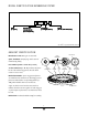
AXLE IDENTIFICATION All axle assemblies are identified with two tags. One located on the differential carrier, and the other located on the right hand side of the axle housing. JULIAN D ATE CODE DA 97 1 70 17 The differential carrier tag contains the following: Dana part number, julian date code, and ratio. Optional items include customer part number, line set number, and the last six digits of the vehicle serial number.
MODEL IDENTIFICATION NUMBERING SYSTEM S 400 S N Famil amilyy (S = Spicer) Nominal Load Carr ying Capacit Carrying Capacityy (400 = 40,000 Lbs.) Gearing T ype Type (S = Single R educ tion) Reduc eduction) Op tions Options (N = *No-SPIN® Differ ential) Differential) * No-SPIN® is a registered trademark of Tractech GEAR SET IDENTIFICATION Manufacturer's Date- Date gear set was made. PINION ETCH SPICER TRADEMARK Spicer Trademark- Company logo and location of manufacturing facility.
AXLE LUBRICANT RECOMMENDATIONS To ensure proper lubrication and operating temperature, correct lubricants and lubricant levels must be obtained.
GENERAL PRECAUTIONS IMPORTANT READ THIS SECTION BEFORE STARTING ANY SERVICE PROCEDURES GENERAL AXLE DESCRIPTION The Spicer tandem rear axle assemblies consist of two heavy duty, hypoid, single reduction differential carrier assemblies. The forward axle contains a power divider, which does exactly what its name implies. It divides power between the forward rear and rear rear axle assemblies.
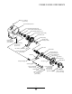
POWER DIVIDER COMPONENTS Fill Plug (35- 45 Lb-Ft) (47-61 N-m) Inter-axle Differential Case Inter-axle Differential Bearing Cup Inter-axle Differential Bearing Cone Inter-axle Differential Side Gear Inter-axle Differential Assembly Helical Drive Gear Needle Bearing Flange Hex Bolt (160-180 Lb-Ft) (217-244 N-m) Needle Thrust Bearing Assembly Magnetic Drain Plug (35- 45 Lb-Ft) (47-61 N-m) Input Shaft Lube Retainer Washer Clutch Collar Hex Bolt (20-25 Lb-Ft) (27-34 N-m) Input Bearing Cone Input Bearing C
FORWARD REAR COMPONENTS Flanged Hex Nut (900-1,200 Lb-Ft) (1,220-1,627 N-m) Output Yoke Assembly Output Oil Seal Axle Shaft ( Roadside ) Beveled Retaining Ring Output Shaft Bearing Output Shaft Fill Plug (35-45 Lb-Ft) (47-61 N-m) Temperature Sensor Plug (35-45 Lb-Ft) (47-61 N-m) Vent Plug Differential Bearing Cap Bolt (295-340 Lb-Ft) (400-461 N-m) Differential Side Bearing Cap Axle Housing Dowel Pin Differential Gear Thrust Washer Differential Case Bolt (180-200 Lb-Ft) (244-271 N-m) Differential Case C
REAR REAR COMPONENTS Housing Vent Plug Axle Shaft ( Roadside ) Fill Plug (35-45 Lb-Ft) (47-61 N-m) Differential Bearing Cap Temperature Sensor Plug (35-45 Lb-Ft) (47-61 N-m) Dowel Pin Magnetic Drain Plug (35-45 Lb-Ft) (47-61 N-m) Differential Bearing Cap Bolt (295-340 Lb-Ft) (400-461 N-m) Nut (300-320 Lb-Ft) (407-434 N-m) Differntial Pinion Mate Thrust Washer Differential Bearing Cap Washer Differential Pinion Mate Differential Cross Shaft Differential Side Gear Ring Gear Flat Washer Differenti
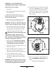
REMOVAL OF DIFFERENTIAL CARRIERS FROM AXLE HOUSINGS NOTE: Steam clean axle assembly. 10. Separate differential carrier from the housing using removal slots. See Figures 1 and 2. Be certain differential carrier clears dowel pins and is balanced properly on jack. Remove top two carrier mounting bolts, and remove differential carrier assembly from the axle housing. 1. Block wheels. 2. Remove axle housing and power divider drain plugs and drain lubricant. 3. Disconnect drive shaft at the rear U-joint.
REMOVAL OF DIFFERENTIAL FROM CARRIER The following service procedures apply for both forward rear and rear rear axles, unless otherwise noted. IMPORTANT: If the ring and pinion is to be reused, ring gear backlash should be checked and recorded before disassembly. Backlash should be reset to this specification after completion of repairs. For backlash specifications refer to DIFFERENTIAL INSTALLATION. 1. Remove adjusting ring bolts and locks from bearing caps. 2.
INTER-AXLE DIFFERENTIAL DISASSEMBLY Fill Plug (35-45 Lb-Ft) (47-61 N-m) Inter-axle Differential Case Bearing Cup Bearing Cone Inter-axle Differential Side Gear Inter-axle Differential Assembly Helical Drive Gear Needle Bearing Needle Bearing Thrust Washer Assembly Bolt (160-180 Lb-Ft) (217-244 N-m) Drain Plug (35-45 Lb-Ft) (47-61 N-m) Lube Retainer Input Shaft Washer Clutch Collar Bolt (20-25 Lb-Ft) (27-34 N-m) Bearing Cone Bearing Cup Shift Fork Shim (Selective) Input Shaft Bearing Retainer Spring
INTER-AXLE DIFFERENTIAL DISASSEMBLY NOTE: Use of a torque multiplier is recommended as torque specification on input flanged hex nut is 9001,200 Lb-Ft (1,220-1,627 N-m). (Refer to RECOMMENDED SERVICE TOOLS, pgs. 29-30) 8. Remove input oil seal 6. Remove input yoke using a suitable puller. See Figure 5. 10. Remove input shaft assembly. Remove input yoke spacer from input shaft. 9. Press out input shaft bearing cup from bearing retainer. Retain shims for possible use during reassembly.
OUTPUT SHAFT DISASSEMBLY Flanged Hex Nut (900-1,200 Lb-Ft) (1,220-1,627 N-m) End Yoke Beveled Retaining Ring Output Shaft Housing Output Shaft Bearing Output Oil Seal 1. Remove the inter-axle drive shaft. 6. Place output shaft remover adapter into housing bore. NOTE: Power divider must be engaged so shaft will not rotate. 7. Thread yoke installer service tool onto output shaft. See Figure 7. 2. Remove output flanged hex nut. 8.
DIFFERENTIAL DISASSEMBLY Bearing Cup Bearing Cone Pinion Mate Thrust Washer Differential Cross Shaft Differential Case Bolt (180-200 Lb-Ft) (244-271 N-m) Plain Half Differential Case Differential Gear Bolt Ring Gear Flange Half Differential Case Flat Washer Nut (300-320 Lb-Ft) (407-434 N-m) Bearing Cup Differential Pinion Mate Gear Thrust Washer Bearing Cone 1. Match mark differential case halves with a punch or chisel for correct alignment in reassembly. See Figure 8.
PINION DISASSEMBLY 1. Remove flanged hex nut. face up. See Figure 10 and 10A. NOTE: Use of a torque multiplier is recommended. Torque flanged hex nut to 900-1,200 Lb-Ft (1,2201,627 N-m). 7. Place a wooden block under pinion to avoid damage of gear teeth during removal. 8. Pinion removal - 2. Remove end yoke on the rear rear axle using a suitable puller. Refer to RECOMMENDED SERVICE TOOLS, pgs. 29-30). 3. Remove the oil seal on the rear rear axle and discard. 4.
CLEANING AND INSPECTION CLEANING GEARS 1. Parts should be cleaned with emulsion cleaners or petroleum base cleaning solvent. NOTE: Alkaline type solutions may cause damage to machined surfaces and should be avoided. 2. Make sure interior of axle housing is clean prior to reassembly. 3. Clean all gasket surfaces of old material. DRYING Use soft, clean, lintless towels or rags to dry components after cleaning. Bearings should not be dried by spinning with compressed air.
PINION ASSEMBLY NOTE: Alkaline type solutions may cause damage to machined surfaces and should be avoided. 3. Stake pilot bearing in nine places using a center punch or equivalent tool. See Figure 13. 4. Press inner and outer bearing cups into the carrier Feeler Gauge Figur 1 iguree 1 11 1. Press inner bearing cone onto pinion. See Figure 11. 2. Press pinion pilot bearing onto the pinion. See Figure 12. Figur 4 iguree 1 14 until seated. Use a feeler gauge (.
PINION ASSEMBLY 5. Place carrier housing in press with the pinion supported by wood block (6"X6"X6"), so the inner pinion bearing is mated to the cup. See Figure 15. 6. Insert original preload spacer and outer pinion bearing onto pinion. Yoke Installer Service Tool 7. Press outer pinion bearing onto pinion until completely seated. 8. On forward rear, press driven gear onto pinion. See Figure 16. IMPORTANT: The old style driven gear on the 3.21 and 3.
PINION ASSEMBLY NOTE: Individual carriers may vary slighty. NOTE: Closer adjustment can be made by sanding the next thicker spacer to desired thickness using emery cloth on a flat surface. Pinion bearing preload spacers are available in the following thicknesses: inch mm inch mm .718 .719 .720 .721 .722 .723 .724 .725 .726 .727 .728 .729 .730 18.24 18.26 18.29 18.31 18.34 18.36 18.39 18.41 18.44 18.47 18.49 18.52 18.54 .731 .732 .733 .734 .735 .736 .737 .738 .739 .740 .741 .742 18.57 18.60 18.
DIFFERENTIAL ASSEMBLY Bearing Cup Bearing Cone Pinion Mate Thrust Washer Differential Cross Shaft Differential Case Bolt (180-200 Lb-Ft) (244-271 N-m) Bolt Ring Gear Plain Half Differential Case Differential Side Gear Flange Half Differential Case Flat Washer Nut (300-320 Lb-Ft) (407-434 N-m) Bearing Cup Differential Pinion Mate Gear Thrust Washer Bearing Cone 1. If ring gear was removed from the differential case, reinstall it at this time.
OUTPUT SHAFT ASSEMBLY End Yoke Flanged Hex Nut (900-1,200 Lb-Ft) (1,220-1,627 N-m) Output Shaft Beveled Retaining Ring Output Oil Seal Housing Output Shaft Bearing 1. Press new bearing onto shaft using output shaft bearing installer service tool. See Figure 19. 3. Install output shaft and bearing assembly into housing using bearing installer service tool withadequate 2 jaw puller. See Figure 20. NOTE: Clean bore of housing to remove old Loctite and oil. 4.
INTER-AXLE DIFFERENTIAL ASSEMBLY 1. Position inter-axle differential case on two 4" x 4" blocks for reassembly Tap nut lightly with soft hammer. 15. Position dial indicator onto end of input shaft. See Figure 21. 2. Install new rear differential bearing cup into case. 3. Press new bearing cone onto rear differential gear. NOTE: Be certain that both cup and cone are seated properly or false reading on end play of inter-axle may occur. 4.
INTER-AXLE DIFFERENTIAL ASSEMBLY 22. Assemble the shift collar onto the shift fork with flat side of collar up. The fork bushing must also face up. Install the fork and collar into the case and align the hole of the shift fork over the opening of the spring. 32. Install new oil seal into input shaft bearing retainer. 23. Apply a thin coat of grease to the small diameter of the shift shaft. of case and around each bolt hole. See Figure 22. 33.
DIFFERENTIAL INSTALLATION 6. Loosen adjusting ring on tooth side of ring gear 1 notch and tighten adjusting ring on flange side of ring gear 1 notch. Repeat process until backlash is elminated. Tighten adjusting ring on tooth side of ring gear until the ring gear and pinion backlash matches the backlash etched on the ring gear. This adjustment sets both the backlash and the bearing preload. 1. Install ring gear and differential assembly into carrier housing.
RING GEAR AND PINION TOOTH CONTACT PATTERN STEP 1. Paint 1/4 ring gear with marking compound on both the drive and coast side. The procedures to the right are to be used to establish proper gear tooth pattern after assembly of the carrier is complete. STEP 2. Rotate ring gear at least one complete revolution in both directions while load is being applied. NOTE: If matched sets are being reused, measure and record backlash before disassembly, and reassemble to the same backlash.
INSTALLATION OF INTER-AXLE DIFFERNETIAL TO CARRIER 1. Thoroughly clean mating face of carrier and apply an 1/8 inch bead of Loctite #518 Gasket Eliminator. See Figure 19 for correct bead pattern. 2. Align inter-axle differential case with carrier housing and insert bolts and torque to 160-180 Lb-Ft (217-244 N-m). #518 Gasket Eliminator Bead Pattern Figur 9 iguree 1 19 YOKE REMOVAL AND SEAL REPLACEMENT 1. Disconnect drive shaft at the rear U-joint. 2. Remove yoke nut.
SHIFT CYLINDER SERVICE DISASSEMBLY 1. Disconnect air line from power divider. 2. Remove shift cylinder cover bolts and washers. 3. Remove cover and O-ring seal. 4. Pull shift cylinder piston assembly from carrier. 5. Inspect all components for wear. NOTE: Do not remove shift fork shaft from assembly.
INSTALLATION OF DIFFERENTIAL CARRIER INTO AXLE HOUSING 7. Install the new axle flange gasket. 1. Thoroughly clean the inside of the carrier housing and inspect the housing mounting surface for nicks and general cleanliness. Stone the surface if necessary to remove burrs or nicks. 8. Install the axle shafts in proper location. Torque the axle flange nuts to vehicle manufacturers specifications. 9. Clean drain plug and fill unit to proper level with hypoid gear lubricant. 10.
AXLE / TORQUE SPECIFICATIONS S400-S Specifications Position U.S. Me tric Metric 10 - 40 Lb-in 1.1 - 4.5 N-m Pinion Torque Bearing Preload (Torque Wrench)* Differential .008 - .012 in. Ring Gear to Pinion Backlash .30 - .40 mm Lubrication (Approx.**) Forward Rear 30 Pts. 14 Liters Rear Rear 25 Pts. 11.7 Liters * Pinion bearing preload is established prior to installation of pinion seal. ** Capacity will vary depending on the housing angle in each vehicle.
RECOMMENDED SERVICE TOOLS ORDER NUMBER ILLUSTRATION DESCRIPTION DST1001 CARRIER STAND TORQUE MULTIPLIERS DST1002 DST1003 Maximum 1,000 Lb-Ft Maximum 2,000 Lb-Ft DST1004 DST1005 Maximum 4,000 Lb-Ft Maximum 12,000 Lb-Ft DST1006 YOKE REMOVER, BAR TYPE DST1007 YOKE INSTALLER (1-3/4"-12) DST1008 LONG, 2-JAW, PULLER 29
RECOMMENDED SERVICE TOOLS DS T1 000 DST1 T1000 S400 SER VICE KIT SERVICE ORDER NUMBER ILLUSTRATION DESCRIPTION DST1000-1 SEAL INSTALLATION HANDLE (To be used with seal installers listed below) DST1000-2 INPUT SHAFT SEAL INSTALLER OUTPUT SHAFT SEAL INSTALLER DST1000-3 PINION SEAL INSTALLER DST1000-4 OUTPUT SHAFT BEARING/ BEARING ASSEMBLY INSTALLER (To be used with 2-jaw puller) DST1000-5 OUTPUT SHAFT REMOVER ADAPTER (To be used with yoke installer DST 1007) ALL SERVICE TOOLS AVAILABLE FROM OTC D
Aftermarket Group ForDana spec‘ing or service assistance, call 1.800.621.8084 or visit our website at www.spicerparts.com PO Box 321 Toledo, Ohio 43697-0321 Warehouse Distributor: Dana Commercial Vehicle1.800.621.8084 Products Group OE Technology Dealers: 1.877.777.5360 3939 Drive Maumee, Ohio, USA 43537 www.spicerparts.com www.dana.com AXSM-1951 Printed in U.S.A. Copyright Dana Limited, 2012. All rights reserved. Dana Limited.