
User's Manual

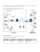

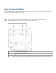

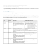
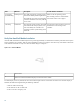
Table Of Contents

Possible Failures and ActionsDescriptionLED ColorState
Failure to start the operating system.
This normally points to a software/build
issue. Please contact Cisco support.
The small cell loads the operating system
and starts the default platform applications.
The small cell moves to the next state (State
5) when it establishes connectivity with the
service node.
Flashing Green4. Operating
System Booting
Any subsequent state transitions can now be
tracked from events and logs on the
controller.
The operating system is running. The small
cell continues the startup sequence, but is
now controlled by the controller. The
operating system is up and running on the
small cell.
Solid Green5. Running
Verify Your Small Cell Module Installation
After the small cell module is installed and powered up, it takes approximately one minute for the module to perform the boot sequence
and be reachable by the controller. Take note of the initialization sequence by noting the color and activity of the LEDs on either side
of the module. The module is ready to use when the LEDs change to solid green.
Figure 5: Cisco Small Cell Module
Reset button1
LED—the same LED indication displays on both sides of the module
2
The LED display is active by default, but can be deactivated in light-sensitive environments as needed. Even when the display is
disabled, the LED will be lighted during the following conditions:
•
while the small cell is booting
•
if the small cell or cell is in fault state
•
if there is an active emergency call
10