
User's Manual
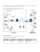

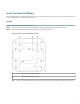

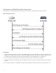
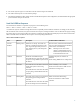
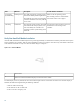
Table Of Contents

5
The arrival sequence begins. The controller sends the software image to the small cell.
6
The small cell boots up the received software package.
7
The small cell establishes an IPsec tunnel with the controller. Based upon the radio configuration, the small cell loads the appropriate
protocol elements and joins the network.
Small Cell LED Boot Sequence
The small cell state machine is sequential and progresses in the following order:
State 0 -> State 1 -> State 2 -> State 3 -> State 4 -> State 5
A normal boot sequence transitions through all these states sequentially and the LED state transitions accordingly. If the small cell
fails to transition to the next state, the system restarts the boot sequence, starting with State 0. You can determine the progress during
the booting stages by observing the LED color transitions. On failure, the last LED state will display the state that encountered the
failure. This table shows the small cell boot sequence and corresponding LED behavior:
Table 2: Small Cell LED Boot Sequence
Possible Failures and ActionsDescriptionLED ColorState
Short lived state; small cell should transition
to the next state immediately and should not
remain in this state indefinitely.
Flashing Green is also used to
indicate a small cell that has been
administratively disabled. This can
be determined from the CLI.
Note
Initial state on startup. The small cell
bootup is controlled by firmware in this
state. It goes through a lamp test in this
state, meaning that it cycles through all
LED colors.
Flashing Green0. Power
On/Reset
No DHCP Response, IP Address not
allocated.
Check cabling, DHCP Server configuration.
Small cell sends DHCP Request.
The small cell moves to the next state (State
2) upon receiving a DHCP response and an
IP Address.
Solid Red1. DHCP
No IP reachability to the controller.
Check IP network between small cell and
controller for routing issues.
The small cell has an IP Address and sends
a UDP Join request to the Serving
controller.
The small cell moves to the next state (State
3) upon getting a JOIN GRANT from the
controller.
Solid Blue2. Join
Failure to download TFTP image.
Check firewall between small cell and
controller.
The small cell proceeds next to download
the operating system image from the
controller.
The small cell moves to the next state (State
4) after the image has been downloaded.
Flashing Blue3. TFTP
9