
User's Manual
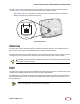
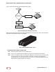


Table Of Contents

SmartCloud Radio Node - SCRN 200 Hardware Installation Guide
SpiderCloud Wireless, Inc.
15
Step 5 The radio node boots up and attempts to connect to the services node. See Boot Sequence
and Services Node Communication on page 15 for details.
Detaching the Radio Node from the Mount Bracket
To remove the radio node from the bracket assembly
Step 1 If needed, remove the padlock or cable tie wrap securing the radio node.
Step 2 Depress the spring clip on the pedestal base and slide the radio node out of the mount
bracket.
Step 3 Detach the RJ-45 clip from the Ethernet port and remove the cable from cable brackets
and cable opening.
Boot Sequence and Services Node Communication
On initial boot, the radio node performs the following boot sequence and communicates with the services
node. This sequence takes about one minute to complete. When completed, all devices are reachable:
Figure 14 Radio Node Boot Sequence
The lock in the above figure is shown schematically. The orientation is for illustration
purposes (not accurate) since the bracket is wall or ceiling mounted.
Note
USB CONSOLE
LK AT LK AT LK AT LK AT LK AT LK AT LK AT LK AT
81234567
LNK ACT
MGMT
POWER STATUS 1 2
SIM 0 SIM 1
Radio Node Services Node DHCP Server
DHCP Request for IP Address
DHCP Response (RN, IP, Controller IP)
Join Request
Join Response (Join Grant, Redirect, Denied)
Arrival sequence begins
Send SpiderCloud software package
Mount package, join the network