
User's Manual

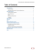
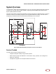
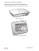
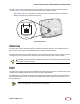
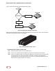
Table Of Contents

SmartCloud Radio Node - SCRN 200 Hardware Installation Guide
SpiderCloud Wireless, Inc.
9
The radio node has one 10/100 Ethernet port that supports a Category 5 (CAT-5) cable with an RJ-45
connector. Figure 4 shows the 10/100 port. There are two LEDs on the connector:
• Link: Steady green state indicates a normal Layer 2 link connection has been established.
• Activity: Yellow blinking indicates data activity.
Figure 4 Ethernet Port
Antennas
The radio node has two vertically-polarized, omnidirectional internal antennas. They radiate power in a
plane normal to their length: horizontal radiation from vertically-oriented antennas.
The radio node operates over a licensed band so it can be placed anywhere inside the building. However,
coverage area is very important. Place the radio node units at strategic points for best coverage.
PoE+
The radio node receives its power from a standard PoE+ switch (typical) or injector. The radio node is fully
compliant with the IEEE 802.3at Power Over Ethernet (PoE+) specification.
Per IEEE 802.3at, use standard CAT-5/5e or better twisted-pair cable with a maximum length restriction of
100 meters (328 feet) for PoE+. This restriction minimizes power loss between the PoE+ power source
and the radio node.
To maximize antenna transmission, SpiderCloud Wireless recommends not installing the radio
node inside a metallic enclosure.
Power is distributed over two pairs of the four available pairs in CAT-5 cables. The radio
node can accept power on either used or un-used pairs.
Ethernet
Port
Link
Activity
Tip
Note