
User's Manual


SpiderCloud Radio Node - SCRN-200 Hardware Installation Guide
SpiderCloud Wireless, Inc.
18
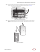
Step 2 Attach a padlock or cable tie wrap through the cutout lock holes in the mount bracket and
pedestal base.
Figure 19 Padlock and Lock Holes
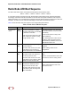
Step 3 The radio node boots up and attempts to connect to the services node. Refer to Boot
Sequence and Services Node Communication below for more information.
Detaching the Radio Node from the Mount Bracket
To remove the radio node from the bracket assembly
Step 1 If needed, remove the padlock or cable tie wrap securing the radio node.
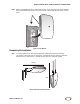
Step 2 Depress the spring clip on the pedestal base and slide the radio node out of the mount
bracket.
Step 3 Detach the RJ-45 clip from the Ethernet port and remove the cable from cable brackets
and cable opening.
The lock in the above figure is shown schematically. The orientation is for illustration
purposes (not accurate) since the bracket is typically wall or ceiling mounted.
Note