
User's Manual


SpiderCloud Radio Node - SCRN-200 Hardware Installation Guide
SpiderCloud Wireless, Inc.
19
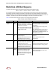
Boot Sequence and Services Node Communication
On initial boot, the radio node performs the following boot sequence and communicates with the services
node. This sequence takes about one minute to complete. When completed, all devices are reachable:
Figure 20 Radio Node Boot Sequence
Sequence description:
1. When the radio node is powered on, the device sends a DHCP Request to the services node
DHCP server to get IP information. The DHCP server is configured on the services node by default
to respond only to DHCP requests from SpiderCloud Wireless radio nodes. Refer to the
SpiderCloud OS (SCOS) Administrator Guide for more information about the services node
DHCP server configuration.
2. The server responds with the IP addresses of the radio node and the services node (the master of
the radio node).
3. Using its own IP address, the radio node sends a Join Request message to the services node. The
radio node seeks to join the cellular network.
4. The services node responds with a Join Response message indicating whether the radio node is
allowed to join the network or not.
5. The arrival sequence begins. Based on the configuration of the radio node, the radio node will join
the system and get its configuration. The services node sends the SpiderCloud software image
(the system image and configuration settings) to the radio node.
6. The radio node reboots and mounts the SpiderCloud software image as a RAM-based file system.
7. The radio node contacts the services node and joins the network.
USB CONSOLE
LK AT LK AT LK AT LK AT LK AT LK AT LK AT LK AT
81234567
LNK ACT
MGMT
POWER STATUS 1 2
SIM 0 SIM 1
Radio Node Services Node
DHCP Request for IP Address
DHCP Response (RN, IP, Controller IP)
Join Request
Join Response (Join Grant, Redirect, Denied)
Arrival sequence begins
Send SpiderCloud software package
Mount package, join the network