
User's Manual


SpiderCloud Radio Node - SCRN-200 Hardware Installation Guide
SpiderCloud Wireless, Inc.
8
• Two orderable options for transmitter output power:
— 100mW (20 dBm) RMS radio power
— 250mW (24 dBm) RMS radio power
Compliance
•ETSI:
— EN 301 489-1
— EN 301 489-23
— EN 301 908-1
— EN 301 908-3
— EN 50385
— EN 60950-1 (safety)
• IEEE 802.3at PoE+
• FCC:
— FCC Part 15 Class A
— FCC Part 24 (UMTS Band II only)
— FCC Part 27 (UMTS Band IV only)
•CE Marking
• NRTL Marking
• RoHS (Directive 2002/95/EC on RoHS)
• R&TTE (Directive 1999/5/EC on R&TTE)
• CB certification as per IEC 60950-1:2011
• Industry Canada: RSS-133, RSS-139, ICES-003 (Class A)
Radio Node Models
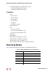
Tabl e 1 displays the orderable configurations of the SCRN-200 radio node:
Table 1: SCRN-200 Radio Node Configurations
Radio Node Model Description
SCRN-200-1 UMTS Band I, Internal antennas
SCRN-200-1E UMTS Band I, external antennas
SCRN 200-2 UMTS Band II, Internal antennas
SCRN-200-2E UMTS Band II, external antennas
SCRN 200-4 UMTS Band IV, external antennas
SCRN-200-4E UMTS Band IV, external antennas
SCRN-200-241 UMTS Band I, Internal antennas, 24dBm