
User's Manual


SpiderCloud Radio Node - SCRN-200 Hardware Installation Guide
SpiderCloud Wireless, Inc.
9
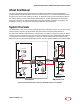
Antennas
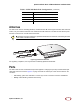
The radio node uses two vertically-polarized, omnidirectional 2 dBi nominal gain antennas. Both antennas
receive, only one antenna transmits. One model has internal antennas. The other has two antenna ports
with TNC connectors for use with external antennas.
Figure 4 Typical External Antennas
For regulatory compliance, use only antennas certified by SpiderCloud Wireless.
Ports
The radio node has one 10/100 Ethernet port that supports a Category 5e (Cat 5e) or better twisted-pair
cable with an RJ-45 connector. Figure 5 on page 10 shows the 10/100 port. There are two LEDs on the
connector:
• Link: Steady green state indicates a normal Layer 2 link connection has been established.
• Activity: Yellow blinking indicates data activity.
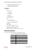
SCRN-200-242 UMTS Band II, Internal antennas, 24dBm
SCRN-200-242E UMTS Band II, external antennas, 24dBm
SCRN-200-244 UMTS Band IV, Internal antennas, 24dBm
SCRN-200-244E UMTS Band IV, external antennas, 24dBm
To maximize antenna transmission, SpiderCloud Wireless recommends not installing the radio
node inside a metallic enclosure.
Table 1: SCRN-200 Radio Node Configurations (continued)
Radio Node Model Description
Tip