
User's Manual


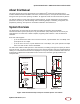

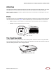
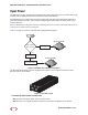
Table Of Contents
- Table of Contents
- About this Manual
- System Overview
- System Specifications
- Radio Node Models
- Antennas
- Ports
- The Top-Panel LED
- Input Power
- Select the Radio Node Location
- Installation and Mount Bracket Assembly
- Boot Sequence and Services Node Communication
- Radio Node LED Boot Sequence
- Radio Node LED Management
- The SpiderCloud Documentation Set
- Appendix A: UMTS Antenna Patterns
- Appendix B: LTE Antenna Patterns

SpiderCloud Radio Node - SCRN-310 Hardware Installation Guide
SpiderCloud Wireless, Inc.
9
Antennas
The radio node includes four integrated antennas: two UMTS antennas and two LTE antennas. The UMTS
radio operates in 1x2 mode with receive diversity. The LTE radio operates in 2x2 mode with MIMO.
Tip:
To maximize antenna transmission, SpiderCloud Wireless recommends not installing the radio node
inside a metallic enclosure.
Ports
The radio node has one 1 Gigabit Ethernet port that supports a Category 5e (Cat 5e) or better twisted-pair
cable with an RJ-45 connector. Figure 4 shows the Ethernet port. There are two LEDs on the connector:
• Link: Steady green state indicates a normal Layer 2 link connection has been established.
• Activity: Yellow blinking indicates data activity.
Figure 4 Ethernet Port
The Top-Panel LED
The radio node has one top-panel tricolor LED to indicate power and status. This is the only LED visible
under normal operating conditions. When the radio node initially boots the LED cycles through a number of
colors and flashing behaviors until it is fully operational.
Figure 5 Radio Node Tricolor LED
Ethernet
Port
Link
Activity
LED