
User's Manual

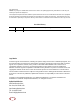


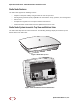


Table Of Contents
- Table of Contents
- About this Manual
- System Overview
- System Specifications
- Radio Node Models
- Antennas
- Ports
- The Top-Panel LED
- Input Power
- Select the Radio Node Location
- Installation and Mount Bracket Assembly
- Boot Sequence and Services Node Communication
- Radio Node LED Boot Sequence
- Radio Node LED Management
- The SpiderCloud Documentation Set
- Appendix A: UMTS Antenna Patterns
- Appendix B: LTE Antenna Patterns

SpiderCloud Radio Node - SCRN-310 Hardware Installation Guide
SpiderCloud Wireless, Inc.
10
Input Power
The radio node receives its power from a standard PoE+ switch (typical) or injector. The radio node is fully
compliant with the IEEE 802.3at Power Over Ethernet (PoE+) specification.
Per IEEE 802.3at, use standard Cat 5e or better twisted-pair cable with a maximum length restriction of
100 meters (328 feet) for PoE+. This restriction minimizes power loss between the PoE+ power source
and the radio node.
Power is distributed over two pairs of the four available pairs in Cat 5e or better cables. The radio node can
accept power on either used or un-used pairs.
Figure 6 on page 10 shows the valid radio node cabling/powering options:
Figure 6 Valid Radio Node Cabling/Powering Options
The illustration below shows a generic single-port PoE+ injector. Use this injector only when a PoE+
Ethernet switch is not available.
Figure 7 Typical PoE+ Injector
To connect the PoE+ injector to a radio node
Step 1 Attach the injector power cord to a power source.
Step 2 Connect an unpowered Ethernet cable from a switch to the IN port on the injector.
Services Node
PoE+ Switch
Out
In
Services Node
PoE+ Switch or
PoE+ Injector
PoE+ Injector
Non PoE+ Switch
OUT
IN
CONNECT
PoEPLUS
ON