
User's Manual


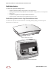


Table Of Contents
- Table of Contents
- About this Manual
- System Overview
- System Specifications
- Radio Node Models
- Antennas
- Ports
- The Top-Panel LED
- Input Power
- Select the Radio Node Location
- Installation and Mount Bracket Assembly
- Boot Sequence and Services Node Communication
- Radio Node LED Boot Sequence
- Radio Node LED Management
- The SpiderCloud Documentation Set
- Appendix A: UMTS Antenna Patterns
- Appendix B: LTE Antenna Patterns

SpiderCloud Radio Node - SCRN-310 Hardware Installation Guide
SpiderCloud Wireless, Inc.
8
Power
The radio node is compliant with IEEE 802.3at (PoE+):
• Power consumption: 23W maximum
• UMTS transmitter output power: 1x 250 mW (24 dBm) RMS radio power
• LTE transmit output power: 2x125 mW (24 dBm)
Compliance
•ETSI:
— EN 301 489-1
— EN 301 489-23
— EN 301 908-1
— EN 301 908-3
— EN 50385
— EN 60950-1 (safety)
• IEEE 802.3at PoE+
• FCC:
— FCC Part 15 Class A
— FCC Part 24 (UMTS Band II only)
— FCC Part 27 (UMTS Band IV only)
•CE Marking
• NRTL Marking
• RoHS (Directive 2002/95/EC on RoHS)
• R&TTE (Directive 1999/5/EC on R&TTE)
• CB certification as per IEC 60950-1:2011
Radio Node Models
Table 1 displays the orderable configurations of the SCRN-310 radio node:
Table 1: SCRN-310 Radio Node Configurations
Radio Node Model Description
SCRN-310-0701 Dual-mode with internal antennas: LTE Band 7, UMTS Band 1
SCRN-310-0402 Dual-mode with internal antennas: LTE Band 4, UMTS Band 2