
Installation Manual


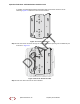


SpiderCloud Radio Node - SCRN-320 Hardware Installation Guide
20
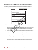
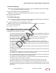
Boot Sequence and Services Node Communication
On initial boot, the radio node performs the following boot sequence. When finished, all devices are
reachable. Figure 17 shows the radio node boot sequence:
Figure 17 Radio Node Boot Sequence
Boot Sequence:
1. When the radio node is powered on, the device sends a DHCP Request to the services node
DHCP server to get IP information. The DHCP server is configured on the services node to
respond only to DHCP requests from SpiderCloud Wireless radio nodes. Refer to the SpiderCloud
OS (SCOS) Administrator Guide for more information about the services node DHCP server
configuration.
2. The server responds with the IP addresses of the radio node and the services node (the master of
the radio node).
3. Using its own IP address, the radio node sends a Join Request message to the services node.
The radio node seeks to join the cellular network.
4. The services node responds with a Join Response message indicating whether the radio node is
allowed to join the network or not.
5. The arrival sequence begins. The services node sends the SpiderCloud software image to the
radio node.
6. The radio node boots up the received SpiderCloud software package.
7. The radio node establishes an IPsec tunnel with the services node. Based upon the radio
configuration, the radio node loads the appropriate protocol elements and joins the network.
USB CONSOLE
LK AT LK AT LK AT LK AT LK AT LK AT LK AT LK AT
81234567
LNK ACT
MGMT
POWER STATUS 1 2
SIM 0 SIM 1
Radio Node Services Node
DHCP Request for IP Address
DHCP Response (RN, IP, Controller IP)
Join Request
Join Response (Join Grant, Redirect, Denied)
Arrival sequence begins
Send SpiderCloud software package
Boot-up, bring up the IPsec tunnel and join the network
DRAFT
SpiderCloud Wireless, Inc. Proprietary and Confidential