D R AF T SpiderCloud® Radio Node - SCRN-330 Hardware Installation Guide Part number: DOC-SCRN-330-HW-01, Rev.
FCC Statements Caution: Any changes or modification cautions to this device not explicitly approved by manufacturer could void your authority to operate this equipment. This equipment complies with FCC radiation exposure limits set forth for an uncontrolled environment. This equipment should be installed and operated with minimum 25 cm between the radiator and your body.
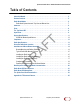
SpiderCloud Radio Node - SCRN-330 Hardware Installation Guide Table of Contents D R AF T About this Manual . . . . . . . . . . . . . . . . . . . . . . . . . . . . . . . . . . . . . . . . . . . . . . . . . . . . . . . . . . . Product Overview . . . . . . . . . . . . . . . . . . . . . . . . . . . . . . . . . . . . . . . . . . . . . . . . . . . . . . . . . . . Radio Node Models . . . . . . . . . . . . . . . . . . . . . . . . . . . . . . . . . . . . . . . . . . . . . . . . . . . . . . . . . .
D R AF T Contents 4 SpiderCloud Wireless, Inc.
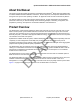
SpiderCloud Radio Node - SCRN-330 Hardware Installation Guide About this Manual This guide provides the system specifications of the SpiderCloud Wireless® Radio Node 330 (SCRN-330). It includes detailed hardware installation instructions, the boot sequence, and expected LED behavior both during the boot-up and under operating conditions. An appendix shows the radio node antenna patterns. The primary audience for this guide includes network planners, system administrators and installation personnel.
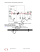
AF T SpiderCloud Radio Node - SCRN-330 Hardware Installation Guide Figure 1 Radio Node Relationship to Enterprise and Mobile Operator Core Networks Radio Node Models Table 1 displays the orderable configuration of the SCRN-330 radio node: D R Table 1: SCRN-330 Radio Node Configurations Radio Node Model SCRN-330-4148 6 Description LTE bands 41 and 48 SpiderCloud Wireless, Inc.
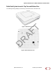
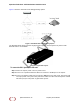
SpiderCloud Radio Node - SCRN-330 Hardware Installation Guide Radio Node System Isometric Top View and Bottom View The following drawings display an isometric top and bottom views of the radio node: D R AF T Figure 2 Radio Node Top View Figure 3 Radio Node Bottom View SpiderCloud Wireless, Inc.
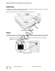
SpiderCloud Radio Node - SCRN-330 Hardware Installation Guide Antennas The radio node includes four internal Tx/Rx antennas with a peak gain of 5dBi and operates in 2x2 mode with MIMO and one internal network listen antenna: T Figure 4 shows the location of the licenced and unlicensed LTE antennas: Ports AF Figure 4 Antenna Band Locations The radio node has one 1 Gigabit Ethernet port that supports a Category 5e (Cat 5e) or better twisted-pair cable with an RJ-45 connector.
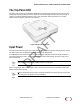
SpiderCloud Radio Node - SCRN-330 Hardware Installation Guide The Top-Panel LED T The radio node has one top-panel tricolor (RGB) LED to indicate power and status. This is the only LED visible under normal operating conditions. When the radio node initially boots the LED cycles through a number of colors and flashing behaviors until it is fully operational. Status indications: boot, normal, disabled, fault, emergency call, radio node tracking.
SpiderCloud Radio Node - SCRN-330 Hardware Installation Guide T Figure 7 shows the valid radio node cabling/powering options: Figure 7 Valid Radio Node Cabling/Powering Options D R AF The illustration below shows a generic single-port PoE+ injector. Use this injector only when a PoE+ Ethernet switch is not available. Figure 8 Typical PoE+ Injector To connect the PoE+ injector to a radio node Step 1 Attach the injector power cord to a power source.
SpiderCloud Radio Node - SCRN-330 Hardware Installation Guide System Specifications The SCRN-330 radio node has the following chassis measurements, power requirements, and environmental requirements, and complies with the following standards. Refer to the feature guide for your services node software release for release-specific features and specifications. Table 2: Radio Node Specifications Height:1.83 cm (7.2 in.) Width: 1.83 cm (7.2 in.) Depth: 36 cm (1.4 in.) Weight 1.23 kg. (2.
SpiderCloud Radio Node - SCRN-330 Hardware Installation Guide Table 2: Radio Node Specifications (continued) Antenna Four internal Tx/RX antennas that operate in 2x2 mode with MIMO One internal network listen antenna or Four antenna ports with SubMiniature version A (SMA) coaxial connectors for external antennas One internal network listen antenna Synchronization IEEE 1588v2-based PTP based frequency synchronization to services node Cellular network listen for phase synchronization to LTE macro eNodeBs
SpiderCloud Radio Node - SCRN-330 Hardware Installation Guide Compliance The SCRN-330 complies with the following standards: Table 4: SCRN-330 Compliance EN 60950-160950 Safety CB certification (IEC 60950, UL 60950-1) EMC/Radio (FCC) FCC Part 15B (Class A) FCC Part 15E FCC Part 24 FCC Part 27 R&TTE Directive 1999/5/EC: • EN 301 489-1, 301 489-23 • EN 301 908-1, 301 908-3, 301 908-14 T • EN 50385 and EN 62311 (SAR) Directive 2011/65/EU AF RoHS Radio Specifications The SCRN-330 has the following
T SpiderCloud Radio Node - SCRN-330 Hardware Installation Guide AF Figure 9 Radio Node Locations When possible, locate radio node units at least 6 meters (20 feet) from an external wall. This distance maximizes indoor coverage and minimizes RF leakage outside the building. Refer to the E-RAN Deployment Planning Guide for Dual-Mode Systems and E-RAN Deployment Planning Guide for LTE Systems for more information about radio node placement.
SpiderCloud Radio Node - SCRN-330 Hardware Installation Guide • When mounting the radio node vertically, orient the bracket such that the bracket keyholes have the narrow side up as shown in Figure 10. Typical Radio Node Mounting Options Radio nodes can be mounted on a wide number of surfaces including the following typical surfaces: Light grill: Use bolts, nuts, and washers to secure the universal mount bracket using holes in the light grill.
SpiderCloud Radio Node - SCRN-330 Hardware Installation Guide T Attach the mount bracket to the radio node as shown in Figure 10: AF Figure 10 Radio Node Slides into Mount Bracket Installing the Radio Node (Method 1) Use this method with the quarter-inch bracket when routing the Ethernet cable through an opening where the bracket will be mounted. To route the cable directly and mount the radio node D R Step 1 Cut a hole in the ceiling or wall to route the Ethernet cable through.
SpiderCloud Radio Node - SCRN-330 Hardware Installation Guide Step 3 With two user-provided screws, attach the mount bracket assembly to a wall or ceiling. The screw holes are sized for an M4 (#10) or larger screw. Ensure the screws have a snug fit onto the studs, sheetrock, anchor, or other material you are bolting onto and that you match the screw head with the appropriate cutout hole size on the bracket. If needed, use a flat washer between the bracket and screw head to ensure a secure fastening.
SpiderCloud Radio Node - SCRN-330 Hardware Installation Guide T If needed, use a flat washer between the bracket and screw head to ensure a secure fastening. Figure 13 shows the 1.25-inch mount bracket. Figure 13 1.25-Inch Mount Bracket D R AF Step 2 Insert the RJ-45 connector through the rectangular bracket opening into the Ethernet port as shown in Figure 14: Figure 14 Route and Terminate the Cable Step 3 Insert the radio node into the mount bracket. 18 SpiderCloud Wireless, Inc.
SpiderCloud Radio Node - SCRN-330 Hardware Installation Guide Completing the Installation Step 1 Attach a padlock or cable tie wrap into the provided slot to secure the unit to the mount bracket. Figure 15 Padlock and Lock Holes T The lock in the above figure is shown schematically. The orientation is for illustration purposes (not accurate) since the bracket is typically wall or ceiling mounted. AF Step 2 The radio node boots up and attempts to connect to the services node.
SpiderCloud Radio Node - SCRN-330 Hardware Installation Guide Boot Sequence and Services Node Communication AF T On initial boot, the radio node performs the following boot sequence. When finished, all devices are reachable. Figure 16 shows the radio node boot sequence: Figure 16 Radio Node Boot Sequence Boot Sequence: D R 1. When the radio node is powered on, the device sends a DHCP Request to the services node DHCP server to get IP information.
SpiderCloud Radio Node - SCRN-330 Hardware Installation Guide Radio Node LED Boot Sequence The radio node state machine is sequential and progresses in the following order: State 0 -> State 1 -> State 2 -> State 3 -> State 4 -> State 5 -> State 6 A normal boot sequence transitions through all these states sequentially and the LED state transitions accordingly. If the radio node fails to transition to the next state, the system restarts the boot sequence, starting with State 0.
SpiderCloud Radio Node - SCRN-330 Hardware Installation Guide Table 6: Radio Node LED Boot Sequence (continued) State LED Color 5. Operating System Booting Flashing Green Description Possible Failures and Actions The radio node loads the operating system and starts the default platform applications. The radio node moves to the next state (State 5) when it establishes connectivity with the service node. 6. Running Solid Green The operating system is running.
SpiderCloud Radio Node - SCRN-330 Hardware Installation Guide * Refer to the SpiderCloud OS (SCOS) Administrator Guide for information about the locate radio node and follow IMSI features.
SpiderCloud Radio Node - SCRN-330 Hardware Installation Guide The Performance Measurements for Dual-Mode Small-Cell E-RANs provides a reference guide to UMTS and LTE Key Performance Indicators (KPI) that monitor the health and state of the ERAN system. • The Performance Measurements for LTE Small-Cell E-RANs provides a reference guide to Key Performance Indicators (KPI) that monitor the health and state of an LTE E-RAN system.
SpiderCloud Radio Node - SCRN-330 Hardware Installation Guide D R AF T Appendix A: LTE Antenna Patterns SpiderCloud Wireless, Inc.
D R AF T SpiderCloud Radio Node - SCRN-330 Hardware Installation Guide 26 SpiderCloud Wireless, Inc.