
Installation Guide

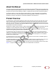
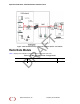
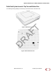
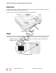
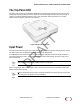
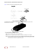
Table Of Contents
- About this Manual
- Product Overview
- Radio Node Models
- Antennas
- Ports
- The Top-Panel LED
- Input Power
- System Specifications
- Compliance
- Radio Specifications
- Select the Radio Node Location
- Installation and Mount Bracket Assembly
- Boot Sequence and Services Node Communication
- Radio Node LED Boot Sequence
- Radio Node LED Management
- The SpiderCloud Documentation Set

SpiderCloud Radio Node - SCRN-330 Hardware Installation Guide
10
Figure 7 sho
ws the valid radio node cabling/powering options:
Figure 7 Valid Radio Node Cabling/Powering Options
The illustration below shows a generic single-port PoE+ injector. Use this injector only when a PoE+
Ethernet switch is not available.
Figure 8 Typical PoE+ Injector
To connect the PoE+ injector to a radio node
Step 1 At
tach the injector power cord to a power source.
Step 2 Connect an unpowered Ethernet cable from a switch to the IN port on the injector.
Step 3 Connect an Ethernet cable from the injector’s OUT port to the radio node. The injector will
now inject power onto a pair of wire pairs in the cable. The radio node will expect a nominal
48V DC input (57V max) from a typical PoE+ injector.
SpiderCloud Wireless, Inc. Proprietary and Confidential
DRAFT