
Installation Guide

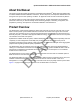
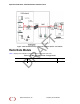
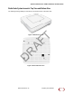
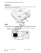
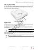
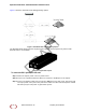
Table Of Contents
- About this Manual
- Product Overview
- Radio Node Models
- Antennas
- Ports
- The Top-Panel LED
- Input Power
- System Specifications
- Compliance
- Radio Specifications
- Select the Radio Node Location
- Installation and Mount Bracket Assembly
- Boot Sequence and Services Node Communication
- Radio Node LED Boot Sequence
- Radio Node LED Management
- The SpiderCloud Documentation Set

SpiderCloud Radio Node - SCRN-330 Hardware Installation Guide
7
Radio Node System Isometri
c Top View and Bottom View
The following drawi
ngs display an isometric top and bottom views of the radio node:
Figure 2 Radio Node Top View
Figure 3 Radio Node Bottom View
SpiderCloud Wireless, Inc. Proprietary and Confidential
DRAFT