
Installation Guide

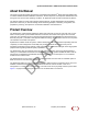
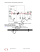
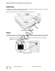
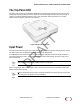
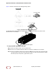
Table Of Contents
- About this Manual
- Product Overview
- Radio Node Models
- Antennas
- Ports
- The Top-Panel LED
- Input Power
- System Specifications
- Compliance
- Radio Specifications
- Select the Radio Node Location
- Installation and Mount Bracket Assembly
- Boot Sequence and Services Node Communication
- Radio Node LED Boot Sequence
- Radio Node LED Management
- The SpiderCloud Documentation Set

SpiderCloud Radio Node - SCRN-330 Hardware Installation Guide
8
Antennas
The radio node inc
ludes four internal Tx/Rx antennas with a peak gain of 5dBi and operates in 2x2 mode
with MIMO and one internal network listen antenna:
Figure 4 shows the location of the licenced and unlicensed LTE antennas:
Figure 4 Antenna Band Locations
Ports
The radio nod
e has one 1 Gigabit Ethernet port that supports a Category 5e (Cat 5e) or better twisted-pair
cable with an RJ-45 connector. Figure 5 shows the Ethernet port. There are two LEDs on the connector:
• Link: Steady green state indicates a normal Layer 2 link connection has been established.
• Activity: Yellow blinking indicates data activity.
Figure 5 Et
hernet Port
SpiderCloud Wireless, Inc. Proprietary and Confidential
DRAFT