D R AF T SpiderCloud® Radio Node - SCRN-340 Hardware Installation Guide Part number: DOC-SCRN-340-HW-01, Rev.
FCC Statements Caution: Any changes or modification cautions to this device not explicitly approved by manufacturer could void your authority to operate this equipment. This equipment complies with FCC radiation exposure limits set forth for an uncontrolled environment. This equipment should be installed and operated with minimum 20 cm between the radiator and your body.
D R AF T About this Manual 5 Product Overview 5 Radio Node Models 6 Radio Node System Isometric Top View and Bottom View 7 Antennas 8 System Specifications 9 SCRN-340 Bracket Specifications 10 Compliance 10 Radio Specifications 11 Ports 11 The Top-Panel LED 12 Input Power 12 Select the Radio Node Location 14 Installation and Mount Bracket Assembly 14 Bracket Mounting and Cabling Guidelines 15 Typical Radio Node Mounting Options 15 Installing the Radio Node 15 Installing the Radio Node (Method 1) 16 Instal
R AF T D
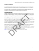
SpiderCloud Radio Node - SCRN-340 Hardware Installation Guide About this Manual This guide provides the system specifications of the SpiderCloud Wireless® Radio Node 340 (SCRN-340). It includes detailed hardware installation instructions, the boot sequence, and expected LED behavior both during the boot-up and under operating conditions. An appendix shows the radio node antenna patterns. The primary audience for this guide includes network planners, system administrators and installation personnel.
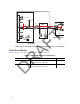
LAN Intranet Radio Nodes PoE+ Switch GNSS Antenna MME Firewall Core Switch IPsec DMZ Security Gateway IPsec S1-C IPsec Backhaul Services Node S1-U S1 PoE+ Switch SGW LTE Mobile Operator Core R AF T Email Web LTE Enterprise Figure 1 Radio Node Relationship to Enterprise and Mobile Operator Core Networks Radio Node Models Table 1 displays the orderable configuration of the SCRN-340 radio node: Table 1: SCRN-340 Radio Node Configurations Radio Node Model 6 Antenna Type Carrier 1: Band
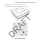
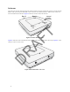
SpiderCloud Radio Node - SCRN-340 Hardware Installation Guide Radio Node System Isometric Top View and Bottom View R AF T The following drawings display an isometric top and bottom views of the radio node: D Figure 2 Radio Node Top View Figure 3 Radio Node Bottom View 7
Antennas The radio node includes four internal Tx/Rx antennas with a peak gain of 5dBi and operates in 2x2 mode with MIMO or two optional ports with QMA coaxial connectors for external antennas. Both models contain one internal network listen antenna. Figure 4 shows the location of the LTE antennas: Band 2 Tx2 Band 1 Tx2 Internal Sniffer Antenna Band 2 Tx1 R AF T Band 1 Tx1 Figure 4 Antenna Band Locations D Figure 5 shows the radio node with external antennas.
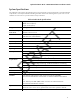
SpiderCloud Radio Node - SCRN-340 Hardware Installation Guide System Specifications The SCRN-340 radio node has the following chassis measurements, power requirements, and environmental requirements, and complies with the following standards. Refer to the feature guide for your services node software release for release-specific features and specifications. Table 2: Radio Node Specifications Height:18.3 cm (7.2 in.) Width: 18.3 cm (7.2 in.) Depth: 36 cm (1.4 in.) Weight 1.23 kg. (2.
SCRN-340 Bracket Specifications The SCRN-340 radio node connects to one of two brackets for ceiling or wall mounting: • a quarter-inch (0.64 centimeter) deep for cabling through a surface such as a wall or ceiling • a 1.25 inch (3.18 centimeters) deep for exposed cabling along a hard surface such as brick or cinder block Table 3 shows the specification for these brackets: Table 3: Bracket Specifications 0.25-Inch Bracket Weight Height:1.57 cm (6.2 in.) Width: 1.3 cm (5.1 in.) Depth: 0.64 cm (0.25 in.
SpiderCloud Radio Node - SCRN-340 Hardware Installation Guide Table 4: SCRN-340 Compliance (continued) EMC/Radio (FCC) FCC Part 15B (Class A) FCC Part 15 Class A FCC Part 24 FCC Part 27 FCC 47 CFR 1.1307(b) FCC 47 CFR 1.
The Top-Panel LED The radio node has one top-panel tricolor (RGB) LED to indicate power and status. This is the only LED visible under normal operating conditions. When the radio node initially boots the LED cycles through a number of colors and flashing behaviors until it is fully operational. Status indications: boot, normal, disabled, fault, emergency call, radio node tracking.
SpiderCloud Radio Node - SCRN-340 Hardware Installation Guide Figure 8 shows the valid radio node cabling/powering options: Services Node PoE+ Switch or PoE+ Injector PoE+ Switch Out PoE+ Injector Services Node R AF T In Non PoE+ Switch Figure 8 Valid Radio Node Cabling/Powering Options The illustration below shows a generic single-port PoE+ injector. Use this injector only when a PoE+ Ethernet switch is not available.
Select the Radio Node Location Radio nodes can be installed in a wide range of locations including walls, ceilings, and spaces above the ceiling. Follow the installation guidelines for selecting appropriate mounting locations for the unit. When mounting a radio node vertically, align the bottom-side fins vertically for superior cooling. Refer to the E-RAN Deployment Planning Guide for information about mounting positioning and the affects on cellular coverage.
SpiderCloud Radio Node - SCRN-340 Hardware Installation Guide Bracket Mounting and Cabling Guidelines Incorrectly cabling and mounting a radio node can result in crushed cables and loss of communications to the unit. Follow these guidelines in cabling the radio node and mounting it on the bracket: • Ensure that the cabling is properly routed and dressed. • Ensure that the radio node is fully inserted into the mount bracket so that it locks into place and is flush.
Attach the mount bracket to the radio node as shown in Figure 11: R AF T Bracket Keyholes Figure 11 Radio Node Slides into Mount Bracket Installing the Radio Node (Method 1) Use this method with the quarter-inch bracket when routing the Ethernet cable through an opening where the bracket will be mounted. To route the cable directly and mount the radio node D Step 1 Cut a hole in the ceiling or wall to route the Ethernet cable through. Align the hole with the bracket Ethernet cable entry hole.
SpiderCloud Radio Node - SCRN-340 Hardware Installation Guide Step 2 Route the Ethernet cable through the rectangular hole in the mounting bracket. R AF T Ethernet Cable Entry Hole Figure 12 Mount Bracket with Direct Cable Routing Step 3 With two user-provided screws, attach the mount bracket assembly to a wall or ceiling. The screw holes are sized for an M4 (#10) or larger screw.
Step 5 Insert the radio node into the mount bracket. Step 6 Push as much cable back through the wall or ceiling as possible. The mount bracket assembly has room for some cable slack. Installing the Radio Node (Method 2) Use this method with the 1.25 inch bracket when routing an exposed Ethernet cable directly to the radio node. To route the cable openly and mount the radio node Step 1 With two user-provided screws, attach the mount bracket assembly to a wall or ceiling.
SpiderCloud Radio Node - SCRN-340 Hardware Installation Guide R AF T Step 2 Insert the RJ-45 connector through the rectangular bracket opening into the Ethernet port as shown in Figure 15: Figure 15 Route and Terminate the Cable Step 3 Insert the radio node into the mount bracket. Completing the Installation D Step 1 Attach a padlock or cable tie wrap into the provided slot to secure the unit to the mount bracket. Figure 16 Padlock and Lock Holes The lock in the above figure is shown schematically.
Detaching the Radio Node from the Mount Bracket To remove the radio node from the bracket assembly Step 1 If needed, remove the padlock or cable tie wrap securing the radio node. Step 2 Slide the radio node out of the mount bracket. Step 3 Detach the RJ-45 clip from the Ethernet port and remove the cable from cable brackets and cable opening. Boot Sequence and Services Node Communication On initial boot, the radio node performs the following boot sequence. When finished, all devices are reachable.
SpiderCloud Radio Node - SCRN-340 Hardware Installation Guide 6. The radio node boots up the received SpiderCloud software package. 7. The radio node establishes an IPsec tunnel with the services node. Based upon the radio configuration, the radio node loads the appropriate protocol elements and joins the network.
Table 6: Radio Node LED Boot Sequence (continued) LED Color State 4. TFTP Flashing Blue Description Possible Failures and Actions The radio node proceeds next to download the operating system image from the services node. Failure to download TFTP image. Check firewall between radio node and services node. The radio node moves to the next state (State 5) after the image has been downloaded. 5.
SpiderCloud Radio Node - SCRN-340 Hardware Installation Guide Table 7: Radio Node LED Behavior (continued) LED Status Blue: fast flashing Locate radio node enabled* Blue: solid Follow IMSI enabled and that IMSI is camped on a cell in the radio node* Off Powered off or LED disabled Flash Rate Approximately 1 second on/off cycle * Refer to the SpiderCloud OS (SCOS) Administrator Guide for information about the locate radio node and follow IMSI features.
The SCOS NB Data Model Reference Guide provides details about the objects and parameters that comprise the system configuration and operational state. • The SpiderCloud OS Faults, Conditions, and Events Reference Guide provides details about all alarms, conditions, and events in the system. • The SpiderCloud System Commissioning Guide provides information about turning up a SpiderCloud E-RAN with the Local Configuration Interface (LCI) graphical user interface.
SpiderCloud Radio Node - SCRN-340 Hardware Installation Guide D R AF T LTE Antenna Patterns 25
LTE Antenna Patterns LTE Band 66 Frequency: 2145 MHz. Peak Gain: 4.10 Dbi. 0º Up 90º R AF T Front Frequency: 2145 MHz. Peak Gain: 2.63 Dbi.