
Installation Guide

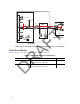
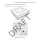
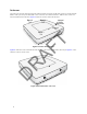
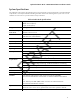
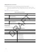
Table Of Contents
- About this Manual
- Product Overview
- Radio Node Models
- Antennas
- System Specifications
- Compliance
- Radio Specifications
- Ports
- The Top-Panel LED
- Input Power
- Select the Radio Node Location
- Installation and Mount Bracket Assembly
- Boot Sequence and Services Node Communication
- Radio Node LED Boot Sequence
- Radio Node LED Management
- The SpiderCloud Documentation Set
- LTE Antenna Patterns

10
SCRN-340 Bracket Specifications
The SCRN-340 radio node connects to one of two brackets for ceiling or wall mounting:
• a quarter-inch (0.64 centimeter) deep for cabling through a surface such as a wall or ceiling
• a 1.25 inch (3.18 centimeters) deep for exposed cabling along a hard surface such as brick or cinder
block
Tab le 3 shows the specification for these brackets:
Compliance
The SCRN-340 complies with the following standards:
Table 3: Bracket Specifications
0.25-Inch Bracket
Dimensions Height:1.57 cm (6.2 in.)
Width: 1.3 cm (5.1 in.)
Depth: 0.64 cm (0.25 in.)
Weight 0.17 kg. (5.8 oz)
1.25-Inch Bracket
Dimensions Height:1.57 cm (6.2 in.)
Width: 1.3 cm (5.1 in.)
Depth: 3.18 cm (1.25 in.)
Weight 0.24 kg. (8.2 oz)
Table 4: SCRN-340 Compliance
European
Safety Safety: EN 60950-1:2006, CB certification (IEC 60950, UL
60950-1)
Health EN 50385:2002
Radio Equipment Directive (2014/53/EU) EN 301 489-50 v2.1.1
EN 301 489-1 v2.1.1
EN 301 908-1 v11.1.1
EN 301 908-3 v11.2.3
EN 301 908-14 v11.2.2
Agency/Marking CE
RoHS Directive 2011/65/EU
North and South American
DRAFT