
Installation Guide


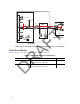
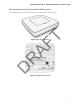
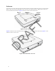
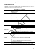
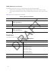
Table Of Contents
- About this Manual
- Product Overview
- Radio Node Models
- Antennas
- System Specifications
- Compliance
- Radio Specifications
- Ports
- The Top-Panel LED
- Input Power
- Select the Radio Node Location
- Installation and Mount Bracket Assembly
- Boot Sequence and Services Node Communication
- Radio Node LED Boot Sequence
- Radio Node LED Management
- The SpiderCloud Documentation Set
- LTE Antenna Patterns

6
Figure 1 Radio Node Relationship to Enterprise and Mobile Operator Core Networks
Radio Node Models
Table 1 displays the orderable configuration of the SCRN-340 radio node:
Table 1: SCRN-340 Radio Node Configurations
Radio Node Model Description Antenna Type
SCRN-340-02041314 Carrier 1: Band 13 or Band 14
Carrier 2: Band 25 or Band 66
Internal
SCRN-340-02041314-EQ Carrier 1: Band 13 or Band 14
Carrier 2: Band 25 or Band 66
External
LAN Intranet
DMZ
Enterprise
Mobile
Operator Core
Email Web
Radio Nodes
IPsec
Backhaul
IPsec
Core
Switch
Firewall
Security
Gateway
IPsec
SGW
MME
LTE
S1-C
S1-U
LT E
S1
PoE+
Switch
PoE+
Switch
Services Node
GNSS
Antenna
DRAFT