
User Manual


RackPack: DynaMaxx
15
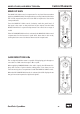
ON, LINK
Control Elements
ON
With the ON button you can turn the device on or off. The ON button is
illuminated when the device is active.
Relay hard bypass circuits ensure signals to be directly switched from
input to output in the case power failures – this “Power Fail Safety“
feature guarantees signal flow in any situation.
If you operate a DynaMaxx module in LINK-Mode, the ON button of the
master module controls both modules. The LINK and ON buttons of the
DynaMaxx module that is currently in LINK mode will thus be illumi-
nated as well—although they have not been activated.
For more information on the LINK mode and the fitting of the LINK
cable please refer to the next part.
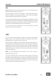
LINK
You can operate two DynaMaxx modules at a time by activating the
LINK mode. You can only run two modules in the LINK mode at a time.
Main applications may be in stereo processing.
When operated in LINK mode, both modules are operated by the mas-
ter module’s control voltage. This ensures a coherent stereo operation.
In LINK mode, all controls of the master module—including the ON and
LINK switch—control the slave module. The master also controls all
switch illuminations on the slave. All controls of the slave module are
inactive in LINK mode.
NOTE: the GAIN REDUCTION LED Display of the slave module is
switched off in Link mode.
If you press the LINK button of the slave module without establishing
the LINK mode through the master module, you will find that the LINK
LED of the master module will not illuminate. This tells you that you
have pressed the wrong LINK button since the controls of the master
module control both devices in LINK mode.
4
*
(
0
7
-
.
"
,
&
6
1
(
"
*
/
$
0
.
1
3
&
4
4
*
0
/
%
:
/
"
.
"
9
9
$
0
.
1
3
&
4
4
0
3
E#
-*/,
0/
%&
$0.
'9
$0.
-*.
(3
4
*
(
0
7
-
.
"
,
&
6
1
(
"
*
/
$
0
.
1
3
&
4
4
*
0
/
%
:
/
"
.
"
9
9
$
0
.
1
3
&
4
4
0
3
E#
-*/,
0/
%&
$0.
'9
$0.
-*.
(3