
User Manual


16
RackPack: DynaMaxx
Control Elements
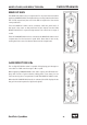
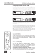
Configuring Modules For Link Mode
On the circuit board of the module you can see two twin dip switches
(top side/approximately center). The switches are labelled with „ON“
and below with „1“ and „2“. Laterally, on the board, there are the labels
„MASTER ONLY“ (left switch) and „MASTER SLAVE“ (right switch).
Master Module: Set both pins of the left MASTER ONLY switch to
the top position (ON). On the right MASTER/SLAVE switch, set pin 1
upwards and pin 2 downwards.
Slave Module: Set both pins of the left MASTER ONLY switch down-
wards. On the right MASTER/SLAVE switch, set pin 1 downwards and
pin 2 upwards.
Now connect both modules with the flat ribbon cable which is provided
with each module that can be driven in LINK mode. For further details
on this connection please refer to the RackPack frame manual.
Note: You have to decide upon the module placement within the
RackPack before you install them. It is customary that the left module
serves as master and the right module serves as the slave.
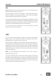
Signal-LED (SIG.)
The SIG. LED indicates that an audio signal reaches the input with a
level above -20 dB. This LED helps the operator especially in complex
setups to determine immediately whether the DynaMaxx actually
receives any signal.
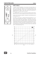
Overload LED (OVL)
The OVL LED indicates a potential internal overload. It
begins illuminating 3 dB ahead of any expected overload
to leave headroom for peak levels, so gaining is perfect in
most cases when the OVL LED is illuminating shortly.
Overloads must be avoided to exclude audible distortions. Permanent
illumination of the OVL LED indicates overloads. Reduce the output
level of source units until the OVL LED goes out or flashes shortly.
LINK Mode/Conguring Modules
4
*
(
0
7
-
.
"
,
&
6
1
(
"
*
/
$
0
.
1
3
&
4
4
*
0
/
%
:
/
"
.
"
9
9
$
0
.
1
3
&
4
4
0
3
E#
-*/,
0/
%&
$0.
'9
$0.
-*.
(3
ON
1 2
ON
1 2
ON
1 2
ON
1 2