User’s Guide Gain Station -30 0 dB 9 18 Clip SOURCE HI PASS Mic 50 Hz Rev. Hi Z Off Nor. NG LEA 22 24AIN ff On Off Peak Off +Fet TPUT LEV U-12-10 -9 -8 -6 E -5 -14 22 -2.5 -16 23 24 -18 0 24.5 -20 2 3.5 25 -22 25.5 5 -24 25.8 5.5 -25 -26 26 6 dB L dB BE GAI TU 18 2021N 12 16 26 9 29 32 7.5 35 6 38 4 41 2.5 46 1 54 b 63 tO e+ Limit 48V IMPED. Ω PHANTOM LIMITER 10k 1.
User’s Guide GainStation 1 Models 2272, 2273 Version 1.0 – 6/2003 Designer: Ruben Tilgner This user's guide contains a description of the product. It in no way represents a guarantee of particular characteristics or results of use. The information in this document has been carefully compiled and verified and, unless otherwise stated or agreed upon, correctly describes the product at the time of packaging with this document.
Contents Introduction .................................................................. 4 Before you begin 7 .......................................................... Rear panel/connections ................................................ 8 Wiring ....................................................................... 8 General advices ......................................................... 9 Connectors and switches ........................................... 10 Optional AD Converter ..............
Introduction Input makes all the difference. Modern audio production relies increasingly on digital systems for recording and mixing processes (DAW‘s, digital consoles etc.). The advantages of digital audio are manifold and include affordable storage, comfortable editing, recall capabilities and automation. On the downside, digital systems still do not offer the same audio qualities and sound characteristics of high-end analog equipment.
Introduction To accommodate portability, the optionally available SPL GainBag ensures safe transport of the GainStation 1 and offers additional storage for cables and an average-sized microphone. For more permanent installations, up to four GainStation 1‘s can be rack-mounted in one optionally available 3-unit rack space mounting frame. Main technical features of the GainStation 1 • Custom-designed and built, fully discrete, class A op-amps (no off-the-shelf stuff here).
Introduction This cutting-edge technology ensures that signals recorded with the GainStation 1 have more presence and substance and will easily cut through a mix even at lower levels. Extremely low-frequency signals are tight and transparent with clear intonation. Percussive transients are interpreted more precisely, which leads to a clearer rhythmic content and in turn a more solid rhythmic performance and perception.
Before you begin It makes good sense to think about where you place your GainStation 1 before connecting it. It should be positioned so that you can easily reach it, but there are other considerations. Try not to place it near heat sources or in direct sunlight, and avoid exposure to excessive vibrations, dust, heat, cold or moisture. It should also be kept away from transformers, motors, power amplifiers and digital processors. In addition, please: • Do not open the case.
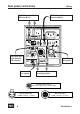
Rear panel/connections Wiring S/P-DIF signal for external synchronization S/P-DIF signal to DAW, HD recorder etc. POWER ON VOLTAGE/FUSE MAINS INPUT 230 V – 50 Hz/315 mA WARNING: TO REDUCE RISK OF FIRE OR ELECTRIC 115 V – 60 Hz/630 mA SHOCK DO NOT EXPOSE THIS UNIT TO RAIN OR MOISTURE OFF CAUTION RISK OF ELECTRIC SHOCK DO NOT OPEN AVIS: RISQUE DE CHOC ÉLECTRIQUE - NE PAS OUVRIR DIG. OUT 24/96 AD SYNC INPUT SAMPLE RATE OPTICAL x2 SPDIF LOCK 2nd signal input of the optional A/D converter 44.
Rear panel/connections General advices Again, while the GainStation 1‘s housing is EMV-proof and protects against HF-interference, placement of the unit is very important since it amplifies microphone signals as well as other unwanted signals. Before connecting the GainStation 1 or any other equipment turn off all power. IMPORTANT: Adjust the voltage setting on the back so that it corresponds with the power conditions.
Rear panel/connections MIC INPUT Dynamic, condenser or tube microphones can be connected to the MIC input. The 48 V switch provides the phantom power necessary for some microphones (see also „Control elements/ Phantom“ on page 16). The MIC input can also be used as a balanced connection for professional audio equipment with a maximum output level of +20 dBu. IMPORTANT NOTE: Always switch the phantom power (48 V) off before connecting anything other than phantom-powered condenser microphones.
Rear panel/connections POWER POWER ON The POWER switch turns the GainStation 1 on (indicated by the blue POWER LED on the front panel) or off. OFF 24/96 AD Converter (optional) DIG. OUT 24/96 AD SYNC INPUT SAMPLE RATE OPTICAL SPDIF LOCK SPDIF x2 44.1 48 The optional 24/96 Converter module (model 2376) provides a digital output for the GS1 in the form of an S/P-DIF output with RCA and optical connectors (in parallel). The converter transmits 24-bit signals.
Rear panel/connections AD IN 2 AD IN 2 AD IN 1 MUTE If the optional 24/96 AD converter module is installed, this input can be used to convert an external analog signal. To avoid clipping, the input level should not exceed +12 dBu (+12 dBu corresponds to full digital gain of 0 dBfs). Excessive input levels are indicated by the AD OVL LED. If no connection is made here, the output signal of the GS1 is routed to both channels of the converter.
Rear panel/connections SYNC INPUT SYNC INPUT The SYNC input allows you to feed an external signal into the converter to control the sample rate. Connect an S/P-DIF output from your master source (e.g. sound card) to the SYNC input. The AD converter will automatically convert to the same sample rate that is received. The 2376 is not equipped to accept Word Clock for synchronization.
Control elements CLEAN GAIN NG LEA 22 24AIN C 19 21 18 16 15 14 13 12 11 10 26 29 32 35 38 41 46 54 63 dB This potentiometer controls the amount of preamplification provided by the class A solid-state stage. A range of up to +63 dB is provided. For more information, please see „Setting levels on the GainStation 1“ on page 19. Mic: +7dB w/transformer IMPORTANT NOTE: If a Lundahl input transformer is installed, add 7 dB to the printed values. TUBE GAIN BE18GAIN TU 12 16 20 21 9 22 23 24 7.
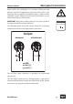
Control elements SOURCE SOURCE Mic This switch allows you to select between the MIC and HI-Z/LINE inputs. Both inputs can remain connected at all times, regardless of which input is selected. Hi Z When first thrown after powering up the unit, this switch can cause a noticeable pop due to the discharge of residual current. This is normal and no cause for concern.
Control elements IMPED. Ω IMPED. Ω 10k 1.2k 200 This 3-way switch allows you to select between three input impedances for the MIC input. The effect varies depending on the microphone used. With dynamic microphones, a lower impedance setting will also reduce the input level—this effect is less pronounced with good condenser microphones. We recommend the 10 k (Ω) setting for most applications, although some microphones may benefit from a different setting.
Control elements LIMITER LIMITER Peak Off +Fet The GainStation 1 offers two types of output level limiting: PEAK and FET. The limiter is pre-output level control, so that the limited signal can be optimally adapted to the internal or external converter. The peak limiter operates with special diodes that convert signal peaks into a type of saturation. Depending on the signal, this allows levels to be effectively and subtly limited.
Control elements POWER-LED Power This LED indicates that the GainStation 1 is connected to the proper AC current and switched on. If the tube stage is active when the unit is switched on, it can take several seconds before a signal can be heard—this time is necessary for the tube to reach operating temperature. -30 0dB 9 18 Clip LED Level Display The level display shows the peak level before output level control. A special circuit allows the LED‘s to vary in brightness to display in-between values.
Operation In spite of its quality and flexibility, the GainStation 1‘s transparent user interface allows quick, intuitive operation. The unit is suited for a wide variety of applications. The following sections will provide an overview of the most important operational concepts and several application examples. Setting levels on the GainStation 1 Start with the limiter switched off.
Operation Combining different amounts of clean and tube gain will create various effects. The GainStation 1 operates virtually distortionfree with the tube stage bypassed. The sound is clean and transparent with extreme detail and very low noise. The clean stage is ideal for most acoustic instruments, as well as jazz or classical recordings. If you activate the tube stage and increase the gain setting slowly, you will notice that once you reach a certain level, harmonic distortion enters the signal.
Operation The peak limiter sounds different with the tube stage activated, since leveling occurs somewhat asymmetrically with the tube in the signal path, so that the negative half-wave is leveled with a much flatter curve. To determine the ideal limiter setting for the internal converter, activate the peak limiting mode and adjust the Clean and/or Tube Gain to a setting well above your working level, so that the Limit LED illuminates brightly. Then reduce the Output Level until the AD OVL LED goes out.
Application examples Next to the obvious recording or sound reinforcement applications, the GainStation 1 is also extremely interesting as an instrument preamp for musicians. Bassists can go through it directly into a power amp, resulting in a sound that is hard to achieve with standard bass preamps, with unparalleled punch, detail and dynamic. (An electric bass was used extensively during development as a „test generator“.
Application examples Vocals/speech The tube stage is well suited for adding presence to vocals. Exercise caution when setting levels, particularly with the clean stage, since vocals can be extremely dynamic. The FET limiter can be very helpful here to level peaks in a subtle, musical fashion and ensure safe levels for AD conversion. Once the limiter is properly set (see ”Limiter”, page 20), tube gain can be added as required.
Application examples Electric Bass If an electric bass is directly connected to the HI-Z input, a combination of clean and tube stages is usually best. In the case of extreme dynamics, the FET limiter will deliver excellent results and a tight, punchy bass sound that usually needs no additional compression. Keyboards/samplers/drum machines Electronic sound sources allow you to fully utilize the GainStation 1‘s potential.
Application examples Drums/snare drum Exercise caution when setting levels to avoid clipping. Drums are notorious for fast, powerful transients that can easily add 10 dB to the average level. In addition, few drummers (or any musicians, for that matter) are so disciplined that they don‘t play louder during a take or concert than they do during sound check. Experiment to see whether or not you like the sound of the tube stage and in what proportion.
Technology Inside the GainStation 1 The most time-consuming part of the development of the GainStation 1 was searching for, selecting and matching components, PCB‘s and IC‘s. One decisive factor in achieving impeccable audio quality is the refusal to accept any weak spots in the chain—the insistence upon each link being as good as the next. It makes no sense to use a world-class op-amp with an improperly engineered power supply or lower-quality passive components such as resistors and condensers.
Technology An output stage, which also operates in class A mode with over 6 mA of closed-circuit current, functions as a current amplifier. The transistors and resistors utilized also had an enormous effect on the audio quality. To facilitate selection, we assembled several models and subjected them to extensive listening tests. All this trouble more than paid off: the final GainStation 1 op-amp has a slew rate of over 100V/us—several times faster than industrial op-amps.
Technology The Hi-Z input is a fully discrete impedance converter that also operates in class A mode. It is based on a low-noise field effect transistor that is especially well suited to this task due to its extremely high input impedance. The signal then passes to the clean gain stage. In order to ensure the shortest possible signal paths, all switching functions are handled by optimally positioned, encapsulated relays with gold-plated contacts—the switches themselves only trigger the relays.
Technology The 2 x 30-V current alone is first pre-regulated to 33 V and then reduced to 30 V in order to filter out the last remnants of hum. This task is handled by select 1000-µF electrolytic capacitors. In addition, critical currents are stabilized via a 100-nF MKP foil condenser, to ensure sufficient current for even the shortest impulses. The transformer is encompassed by double shielding to keep magnetic stray fields to an absolute minimum.
Technical specifications Frequency response (Clean Gain 30 dB, Tube Gain off, output level 0 dB, +/- 0.5 dB): ‹1 Hz-125 kHz Frequency response (Clean Gain 30 dB, Tube Gain off, output level 0 dB, +/- 3 dB): ‹1 Hz-310 kHz Frequency response (Clean Gain 30 dB, Tube Gain 1 dB, output level 0 dB, +/- 0.5 dB): ‹1Hz-125 kHz THD+N (Clean Gain 24 dB, Tube Gain off, output level +6 dB, 20-22 kHz, +25 dBu out): 0.0005 % THD+N (Clean Gain 23 dB, Tube Gain 1 dB, output level +6 dB, 20-22 kHz, +25 dBu out): 0.
Dimensions/weight Dimensions (W x H x D): 106 x 122 x 271 mm Weight (w/o Lundahl transformer and AD converter): 2.
Warranty SPL products are manufactured using carefully selected components and materials and state-of-the-art production technology. Every SPL product is thorough inspected and tested before leaving the factory, including acoustic and electronic testing. SPL warrantees the SPL 24/96 AD Converter Model 2376 to be free of defects in materials or workmanship for a period of 24 months after the date of purchase.
Notes ............................................................... ............................................................... ............................................................... ............................................................... ............................................................... ............................................................... ............................................................... .........................................................
User’s Guide GainStation 1, Models 2272 & 2273 All you need is imagination, good ears and three letters: