
User Manual

12
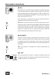
GainStation 1
AD IN 2
If the optional 24/96 AD converter module is installed, this input
can be used to convert an external analog signal. To avoid clip-
ping, the input level should not exceed +12 dBu (+12 dBu corre-
sponds to full digital gain of 0 dBfs). Excessive input levels are
indicated by the AD OVL LED.
If no connection is made here, the output signal of the GS1 is
routed to both channels of the converter.
TIP: AD I N 2 can al s o b e us ed a s an ins er t f or ex ter na l p re -conver-
sion processing. Connect the analog outputs of the GainStation 1
to the external processor‘s inputs and the processor‘s outputs
to AD IN 2 on the Gain Station 1. One channel of the converter
output will contain the dry or unprocessed signal, while the
other channel will contain the processed signal.
AD IN 1 MUTE
Channel 1 of the converter is internally connected to the analog
output, so that the AD OVL LED is always active. If the converter
is not being used, this connection can be bypassed via the AD
IN 1 MUTE switch so that the LED does not continuously blink or
illuminate.
TIP: If no converter is installed, this switch should always be
activated.
DIG. OUT
The converted S/P-DIF signal is routed in parallel to the RCA
and optical outputs. The signal is in professional format with no
sample rate data in the status block.
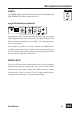
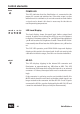
Rear panel/connections
AD IN 2
AD
IN 1
MUTE
AD IN 2
AD
IN 1
MUTE
OPTICAL
SPDIF
DIG. OUT
24/96 AD