Gemini Mastering M/S Processor Manual
Content Gemini Version 1.
Content Control Elements 1 Active 2 Insert (MID) 3 Solo (MID) 4 Balance & Trim 5 Balance 6 Trim 7 Insert (SIDE) 8 Solo (SIDE) 9 Filter & Width 10 Stereo Width 11 Elliptical Filter Specifications 12 12 12 13 13 14 14 14 14 14 15 15 16 Measurements 16 Security Advices Notes on Environmental Protection 17 18 Contact 19 Copy template settings 20
Version 1.1 – 03/2019 Developer: Bastian Neu This manual includes a description of the product but no guarantee as for specific characteristics or successful results. Unless stated otherwise, everything herein corresponds to the technical status at the time of delivery of the product and user manual by SPL electronics GmbH. The design and circuitry are under continuous development and improvement. Technical specifications are subject to change.
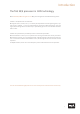
Introduction The first M/S processor in 120V technology With Gemini M/S Mastering Processor M/S processing enters the SPL Mastering series. Gemini is an M/S Encoder and Decoder. Mid signals (voice, snare, bass …) can clearly be seperated from side signals (guitar, spatial sounds, cymbals …) and can individually be processed. When working on the sum signal, M/S coding often is the best way to specifically get access to individual elements within a mix.
Technical Aspects 120 Volt Technology SPL‘s goal was to push analog signal processing to the limits. That‘s why we combined the best possible components with a high-grade optimized circuit design. We have been using the in-house developed 120 Volt technology - the highest-ever operating voltage used for audio applications - in all our products from the Mastering series for years.
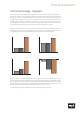
Technical Aspects 120 Volt Technology - Diagrams These diagrams clearly show the advantages of our 120-volt technology in comparison to other circuits with a lower operating voltage. The direct relation between operating level and maximum level is fundamental for the classification: the higher the operating level, the higher the maximum level a circuit can handle.
Installation Voltage Selection Before connecting the Gemini Mastering M/S Processor to the mains, make sure that the voltage selection corresponds to the values of your local power grid (230 or 115 volts). Inside the power connector, to the right, next to the on/off switch, there is an opening that displays the voltage selected.
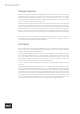
Cabling: Rear Side XLR inputs and outputs We used exclusively Switchcraft/Neutrik XLR input and output plugs to guarantee perfect connectivity in the studio. They provide an optimal connection thanks to their electromechanical design and large contact surface. The image shows the XLR connectors pinout. They are balanced and have three conductors or wires. Conductor 2 (Pin 2) corresponds to the (+) or hot Signal.
Cabling: Rear Side DO NOT OPEN AT T E N T I O N RISQUE DE CHOC ÉLECTRIQUE GND LIFT C AUTION RISK OF ELECTRIC SHOCK NE PA S OU V RIR GND LIFT GND Serial Number VOLTAGE SELECT 115V: T 2 A L 250V 230V: T 1 A L 250V Gemini FUSES MADE IN GERMANY Model 1720 GND LIFT 6 1 Inputs 2 Sends 3 Returns 4 Outputs 5 Ground-Lift (see details on page 7) 6 Voltage (see details on page 6) 1 Inputs Gemini provides two balanced inputs labeled as Inputs. These are female XLR jacks.
Cabling: Rear Side SENDS RETURNS OUTPUTS L SIDE MID SIDE SIDE MID MID R SIDE INPUTS L MID R L GND R ND LIFT ND D LIFT R OUTPUTS 4 RETURNS 3 SENDS 2 INPUTS L 1 We also provide a Screenshow video manual on the product page on our website: https://gemini.spl.audio 3 Returns Additionally, Gemini provides two balanced input jacks, XLR female, labeled as Returns. Connect the left channel to RETURN MID and the right channel to RETURN SIDE.
Cabling: Rear Side Pairing Gemini and DMC INPUT 3 L R SPEAKERS A SPEAKERS B SPEAKERS C SOURCE 2 SPEAKER D Mono R L R L R L Mono R L R L R L SPEAKER D SPEAKERS C SPEAKERS B INPUT 2 L R R R L L RECORDING OUT 2 INPUT 4 R L RECORDING OUT 2 SPEAKERS A INPUT 1 L R R L L L/R to MC16 RECORDING OUT 1 L R L R SUB SOURCE 3 L R PHONITOR/HP OUT R L Mono SUB SOURCE 1 Mono SOURCE 1 L L R R R SOURCE 4 R SUB/MONO FUSES METERING OUTPUTS PHONITOR/HP OUT L
Cabling: Rear Side Pairing Gemini and Hermes Hermes and Gemini Mastering M/S Processor operate in their complete range of functions as stand-alone devices. A pairing of Hermes and Gemini enables lots of further possibilities. If the M/S Encoder and Decoder stages of Gemini are each paired with an insert of Hermes, it is possible to freely choose a position for the M/S Encoder and Decoder within the processing chain.
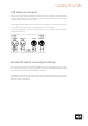
Control Elements 3.5 2.4 3.5 dB 6 2.0 MID 3.0 3.0 2.4 M/S 0.5 33 1.5 5 0 -1.0 4 -1.5 3 5 -0. 0 -2. 2 0.7 1.5 1 TRIM BAL A0NCE 0.7 -2.5 Balance & Trim 2.5 Solo 1.5 Insert 1.0 Active dB 120 V DC Audio Rail 1 Active 2 Insert (MID) 3 Solo (MID) 4 Balance & Trim 5 Balance 6 Trim 1 Active With this button, you activate the M/S Matrix of Gemini. If the button lights up, the M/S Matrix is active.
EREO0 WIDTH ST0 1. IPTIC FILTE EL5L 120 15R -1. -3.5 0 -5. -5.5 55 33 Solo Insert Gemini 9 8 7 mastering m/s processor 5.0 25 10 3.6 390 0 45 22 Hz Filter & Width 2.0 320 11 0 -2.0 0 5.5 10 210 dio Rail Control Elements dB SIDE Model 1720 7 Insert (SIDE) 8 Solo (SIDE) 9 Filter & Width 10 Stereo Width 11 Elliptical Filter We also provide a Screenshow video manual on the product page on our website: https://gemini.spl.
Control Elements 5 Balance With the BALANCE control, you can perfectly place the mid part of the stereo signal in the center of the stereo. The BALANCE control features a very high-resolving radius of +/- 3.5dB. When hard left, the mid signal is shifted to the left by 3.5dB within the stereo signal. When hard right accordingly to the right side. 6 Trim With the TRIM control, you can adjust the level of the mid signal. The TRIM control has a resolution of +/- 2.5dB.
Control Elements 10 Stereo Width With the STEREO WIDTH control, you can increase or attenuate the level of the side signal by 5.5dB. This way, you can change the perception of the stereo width. 11 Elliptical Filter The ELLIPTICAL FILTER (Cauer Filter) removes signal components below a predefined frequency from the side signal. You can then hear these signal component through the M/S decoding in the mid signal component. The ELLIPTICAL FILTER has an extremely steep slope.
Specifications Measurements Inputs Max. Input Level ...................................................................... + 32.5 dBu Input Impedance ...................................................................... 20 kOhms (bal.) Outputs Max. Output Level .................................................................... + 32.5 dBu Output Impedance .................................................................... ‹ 100 Ohms (bal.
Security Advices Connections Only use the connections as described. Other connections can lead to health risks and damage the equipment. Water and humidity Do not use this device anywhere near water (for example in a bath room, a damp cellar, near swimming pools, or similar environments). Otherwise your are dealing with an extremely high risk of fatal electrical shocks! Insertion of objects or fluids Be careful to not insert any object into any of the chassis openings.
Security Advices Controls and switches Operate the controls and switches only as described in the manual. Incorrect adjustments outside safe parameters can lead to damage and unnecessary repair costs. Never use the switches or level controls to effect excessive or extreme changes.
Contact SPL electronics GmbH Sohlweg 80 41372 Niederkrüchten Fon +49 (0) 21 63 98 34 0 Fax +49 (0) 21 63 98 34 20 E-Mail: info@spl.audio Follow us on our Blog, Youtube, Twitter, Instagram and Facebook: Website & Blog: spl.audio Facebook: facebook.spl.audio Instagram: instagram.spl.audio Twitter: twitter.spl.audio Videos: youtube.spl.
M/S MID Balance & Trim dB 0.7 BAL A0NCE 0.7 2.4 -1.0 -1.5 1.5 2.4 3.0 5 -0. dB 0 TRIM 0.5 1.5 0 -2. 120 V DC Audio Rail Date: 10 0 Hz IPTIC FILTE EL5L 120 15R Track(s)/Groups: 55 33 1.5 320 25 Solo 3.5 Insert 3.5 Active -2.5 Titel: 2.5 Album: 22 1.0 -2.0 -3.5 Engineer: 0 45 Artist: -1. dB 0 EREO0 WIDTH ST0 1. -5.5 Copy Master: Recall Settings 5.5 210 3.6 0 -5. 2.0 5.0 390 2.0 3.