
User Manual


10
MTC 2381
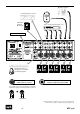
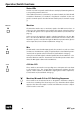
Status LEDs
An LED over each front panel switch indicates activity by illuminating when its
corresponding switch is turned on.
If the Talkback function is activated by an external switch, the Talk LED will
nonetheless illuminate (a footswitch or key/button connected via the rear
panel Footswitch Input is described in Rear Panel Inputs/Footswitch on page
7).
Musician
The Musician switch routes a musician’s signal to the MTC monitor buss. In
such cases, the Source Blend control adjusts this signal’s volume in relation
to the Mix/2Tr (please refer to Operation/Control functions/Source Blend on
page 13).
In this process the musician’s signal is switched parallel into the Cue Mix
buss—also when the Musician switch is deactivated. Here the volume of the
musician’s signal is controlled through the Musician potentiometer (please
refer to Operation/Control Functions/Musician on Page 12).
Mix
The Mix switch routes the Mix input signal to the monitor buss, whose volume
(in relation to the Musician’s signal) is regulated by the Source Blend potenti-
ometer (refer to Operation/Control Functions/Source Blend on Page 13).
In this process the Mix signal is switched parallel into the Cue Mix buss—also
when the Musician switch is deactivated. Here the Mix potentiometer deter-
mines the Mix signal volume in the Cue Mix buss.
2Tr A bis 2Tr D
These switches activate the corresponding stereo A-D inputs and route them
to the monitor buss. The Source Blend potentiometer regulates the this
signal’s volume relative to the Musician’s signal (please refer to Operation/
Control Functions/Source Blend on Page 13).
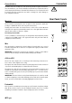
Musician, Mix and 2Tr A to 2Tr D Switching Sequences
These switches can be activated in two or altogether to determine routing for
monitor buss summing. This selection process also determines which signals
appear at the Slave Out output. Possible level differences must be compen-
sated for at the source units.
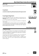
Operation/Switch Functions
2Tr A
Musician
Mix