PQ Mastering Equalizer Manual
Content PQ Version 1.3 – 04 / 2017 Package Contents 2 2 Introduction 3 King of the parametric equalizers 3 Technical Aspects 4 120 Volt Technology 120 Volt Technology - Diagrams 4 5 Installation 6 Voltage Selection First Steps 6 6 Cabling: Rear Side 7 XLR inputs and outputs Ground Lift switch to avoid ground loops 7 7 Control Elements 9 Gain 10 1/4 Gain 10 Frequency 10 LF, LMF, MF, MHF, HF -Button (orange) 10 Q 10 Prop.
Version 1.3 – 04 / 2017 Developer: Wolfgang Neumann / Bastian Neu This manual includes a description of the product but no guarantee as for specific characteristics or successful results. Unless stated otherwise, everything herein corresponds to the technical status at the time of delivery of the product and user manual by SPL electronics GmbH. The design and circuitry are under continuous development and improvement. Technical specifications are subject to change.
Introduction King of the parametric equalizers The PQ Mastering Equalizer is a fully parametric, dual-channel five-band equalizer. The PQ Mastering Equalizer – Model 1540/1544 is a new revised edition of the wellknown SPL PQ Mastering Equalizer – Model 2050. Both units are based on our 120V Rail Technology. The new PQ features the same high-quality characteristics as the previous model.
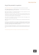
Technical Aspects 120 Volt Technology SPL‘s goal was to push analog signal processing to the limits. That‘s why we combined the best possible components with a high-grade optimized circuit design. We have been using the in-house developed 120-volt technology - the highest-ever operating voltage used for audio applications - in all our products from the Mastering series for years.
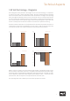
Technical Aspects 120 Volt Technology - Diagrams These diagrams clearly show the advantages of our 120-volt technology in comparison to other circuits with a lower operating voltage. The direct relation between operating level and maximum level is fundamental for the classification: the higher the operating level, the higher the maximum level a circuit can handle.
Installation Voltage Selection Before connecting the PQ to the mains, make sure that the voltage selection corresponds to the values of your local power grid (230 or 115 volts) Inside the power connector, to the right, next to the on/off switch, there is an opening that displays the voltage selected. If the voltage indicated does not correspond to the one required, change it by following this procedure: Open the power connector lid with a small screwdriver (use the tiny slots on the right hand side).
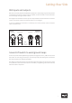
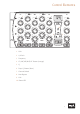
Cabling: Rear Side XLR inputs and outputs We used exclusively Switchcraft/Neutrik XLR input and output plugs to guarantee perfect connectivity in the studio. They provide an optimal connection thanks to their electromechanical design and large contact surface. The image shows the XLR connectors pinout. They are balanced and have three conductors or wires. Conductor 2 (Pin 2) corresponds to the (+) or hot Signal.
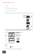
Cabling: Rear Side 1 Input 2 Output 3 Ground Lift (see details on page 7) 4 Voltage (see details on page 6) n: se Holder ses XLR WIRING: INPUT 1 Balanced +4dBu 1 = GND 2 = HOT (+) 3 = COLD (–) A L 250 V .15 A L 250 V 1 OUTPUT 1 2 Q INPUT 2 1 al er ermany OUTPUT 2 GND LIFT GND AC MAINS Voltage Selection: 4 1. Remove Fuse Holder 2. Change Fuses 3. Flip Over 4. Reinstall Fuses: AC MAINS 115V AC: T 6 A L 250 V 230V AC: T 3.15 A L 250 V ~ 115V AC / ~230V AC, 50 Hz / 60 Hz, P max.
Control Elements 1/ Gain 4 LF – 2 1/ Gain 4 – -2 -3 -4 -5 -7 -9 -13 -18 -20 -1 0 1 + 2 -2 -3 -4 -5 -7 -9 -13 -18 -20 -1 0 1 + 2 1 2 1/ Gain 4 MF 2 3 4 5 6 8 12 18 – -2 -3 -4 -5 -7 -9 -13 -18 -20 1/ Gain 4 – -1 0 2 + 1 -1 0 1 + 2 2 1/ Gain 4 HF 1 2 3 4 5 6 8 12 18 LF 1/ Gain 4 – -1 1/ Gain 4 0 – + 1 -2 2 -2 2 -3 3 -3 3 -4 4 -4 4 20 dB -5 5 -5 5 -7 6 -7 6 -9 8 -9 8 140 170 190 1k3 1k6 1k8 110 1k0 220 2k1 -13 12 -13 12 83 770 270 2k6 -18 18 -18 18 66 630 3
Control Elements Gain The amplitude setting ranges from -20 dB up to +20 dB. This means that you can increase or attenuate the amplitude to a maximum of 20 dB. The maximum increase or attenuation also depends on the selected Q-Characteristic. 1/4 Gain Thanks to the 1/4 Gain-Switch, you can reduce a maximum increase or attenuation of the amplitude by the factor 3/4, which regulates the potentiometer from max +/- 20 dB to +/-5 dB cut.
Control Elements Prop. Q -Button (blue) Thanks to this button, each of the 10 filter bands can be set from Constant-Q mode (light off) into Proportional-Q mode (button lights up). Proportional-Q mode / Constant-Q mode Each frequency band consists essentially of two fully parametric equalizers: one for constant Q mode and one for proportional (or variable) Q mode, selectable per band.
Specifications Measurements Inputs Max. Input Level ..................................... + 32,5 dBu Input Inpedance ..................................... 20 kOhms (balanced) Outputs Max. Output Level .................................. + 32,5 dBu Output Inpedance .................................. ‹ 600 ohms (balanced Harmonic Distortion: at -30 dBu: 0,2% at -20 dBu: 0,05% at 0 dBu: 0,01% at +10 dBu: 0,002% at +30 dBu: 0,0005% Noise (unweighted, at 24 dBu, Band 1-5 ON, B/C = 0) ............................
Security Advices Connections Only use the connections as described. Other connections can lead to health risks and damage the equipment. Water and humidity Do not use this device anywhere near water (for example in a bath room, a damp cellar, near swimming pools, or similar environments). Otherwise your are dealing with an extremely high risk of fatal electrical shocks!! Insertion of objects or fluids Be careful to not insert any object into any of the chassis openings.
Security Advices Controls and switches Operate the controls and switches only as described in the manual. Incorrect adjustments outside safe parameters can lead to damage and unnecessary repair costs. Never use the switches or level controls to effect excessive or extreme changes.
Contact SPL electronics GmbH Sohlweg 80 41372 Niederkrüchten Fon +49 (0) 21 63 98 34 0 Fax +49 (0) 21 63 98 34 20 E-Mail: info@spl.info Follow us on our Blog, Youtube, Twitter, Instagram and Facebook: Website & Blog: spl.info Videos: youtube.spl.info Twitter: twitter.spl.info Instagram: instagram.spl.info Facebook: facebook.spl.info © 2016 SPL electronics GmbH This document is the property of SPL and may not be copied or reproduced in any manner, in part or fully, without prior authorization by SPL.
0 1 2 + 0 1 2 4 5 6 8 12 18 3 + – -1 1/ Gain 4 0 1 2 MF + 1/ Gain 4 -2 -3 -4 -5 -7 -9 -13 -18 -20 – -1 0 1 2 + HF 4 5 6 8 12 18 3 -1 1/ Gain 4 – 0 1 2 + Prop Q Con Q 0.6 5.4 0.1 0.7 0.2 4.8 12 0.8 6.7 0.9 0.6 1.1 0.3 15 2.1 Hz 1.5 1.5 1.0 3.5 3.8 2.3 Q f 4 5 6 8 12 18 3 5.4 12 Prop Q Con Q 0.6 LMF 15 0.8 0.1 0.7 0.2 0.3 4.8 3.5 6.7 Q f 5.4 12 4.8 6.7 3.5 3.8 2.3 15 2.1 Q f Hz Prop Q Con Q 1.5 1.5 1.0 0.6 0.1 0.7 0.2 0.