Manual Transpressor Model 1080 Dynamic Processor
Manual Transpressor, Model 1080 Version 1.0 – 7/2010 Developer: Jens Gronwald This manual contains a description of the product. It in no way represents a guarantee of particular characteristics or results of use. The information in this document has been carefully compiled and verified and, unless otherwise stated or agreed upon, correctly describes the product at the time of packaging with this document.
Content Symbols and Notes 4 Scope Of Delivery and Packaging 4 Important Security Information 4 Hook Up 5 Introduction 6 Dual Dynamic Processing 6 Use, Applications, Special Technical Features 7 Rear Panel 8 Signal Connections, Input and Output Electronics, 1/4" Jacks, XLR sockets 9 Power connection and fuse, Voltage Selector 9 Power Switch, GND Lift 9 Balanced connections, Unbalanced connections 10 Input, Sidechain, Stereo Link/Slave, Output 1 & Output 2 11 Operation
Symbols and Notes N THIS MANUAL A LIGHTNING SYMBOL WITHIN A TRIANGLE WARNS YOU ABOUT THE POTENTIAL FOR DANGEROUS ELECTRICAL SHOCKS – WHICH CAN ALSO OCCUR EVEN AFTER THE MACHINE HAS BEEN DISCONNECTED FROM A POWER SOURCE. AN EXCLAMATION MARK (!) WITHIN A TRIANGLE IS INTENDED TO MAKE YOU AWARE OF IMPORTANT OPERATIONAL ADVICE AND/OR WARNINGS THAT MUST BE FOLLOWED. BE ESPECIALLY ATTENTIVE TO THESE AND ALWAYS FOLLOW THE ADVICE THEY GIVE.
Important Security Information Lightning: Before thunderstorms or other severe weather, disconnect the machine from wall power (but to avoid life threatening lightning strikes, not during a storm). Similarly, before any severe weather, disconnect all the power connections of other machines and antenna and phone/network cables which may be interconnected so that no lightning damage or overload results from such secondary connections.
Introduction Dual Dynamic Processing In the late 1990’s SPL revolutionized audio dynamic processing with a groundbreaking new technology. The Transient Designer made it possible, for the first time, to act on the signal in order to amplify or attenuate its transient and to extend or shorten its decay, without affecting the signal level. Thus, dynamic processing that used to be linked to a given threshold became a more powerful sound-shaping tool focused exclusively on the signal’s attack.
Introduction Use • Live and in the studio as an ultraversatile and multifunctional one-channel dynamic processing tool. • Link function for stereo processing with two units. Applications • Comprehensive corrective and creative dynamic processing for all sorts of instruments and vocals. • The use of both modules is specially suited for processing dynamic signals like percussion instruments, bass, guitar, piano, etc.
2 3 PUSH 1 1 3 2 Further Insert Returns, other FX units ... Pin wiring XLR output sockets: 1=GND, 2=hot (+), 3=cold (-) Pin wiring XLR input sockets: 1=GND, 2=hot (+), 3=cold (-) Make sure that the voltage switch setting reflects the correct local power line voltage. Insert Returns (Console, DAW, etc.
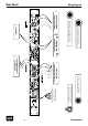
Rear Panel Connections & Switches Signal Connections Turn off the unit before connecting or disconnecting any cable or equipment to it. Otherwise you risk the possibility of damaging your ears or equipment. Input and Output Electronics The input and output electronics of the Transpressor use bridge circuits that keep the signal flow constant, regardless of malfunctioning equipment and power outages (Hard Bypass). The bridge circuits rely on high-quality relays.
Rear Panel Balanced and unbalanced connections Balanced connections It is impossible to exclude interferences when a single audio signal is transmitted. Shielding is effective against electric, but not against electromagnetic influences. Motors, transformers, and alternating current can always induce interferences. But even if the transmission would succeed, differences in ground potentials between driver and receiver would produce disturbances.
Rear Panel Inputs and Outputs Input The balanced XLR and 1/4" inputs serve to connect signal sources to the Transpressor. The Line inputs’ maximum input level is +21 dBu. The XLR and 1/4" inputs are connected in parallel, which means that they should not be used simultaneously. Use the “+4 dBu/-10 dBV” switch to change the input sensitivity. Low level signals are amplified approximately 7.8 dB at the input stage when the sensitivity is set to -10 dB.
Operation Overview Overview The control elements on the front panel of the Transpressor are divided into four sections: Transient Designer, Twin Core Compressor, Parallel Mix and Push Buttons. 12 1. The Transient Designer is very appealing due to the simpleness in its concept of dynamic waveform shaping. With only two controls you can shape the attack and decay of a signal. 2.
Transient Designer Control Elements The Transient Designer You just need to adjust two controls per channel in order to shape the attack and decay of a signal: the Attack control can amplify or attenuate a signal up to 15 dB; while the SUSTAIN control extends or shortens the signal’s decay up to 24 dB. These simple options provide you with amazingly new dynamic processing possibilities.
Control Elements Twin Core Compressor The Twin Core Compressor The Twin Core Compressor is based upon our proven Double VCA Drive. A differential stage eliminates side effects and the half load per VCA dramatically reduces THD values. A large set pf parameters offers a wide range of control.
Twin Core Compressor Control Elements ATTACK with cruise control: AUTO mode The disadvantage of a usual ATTACK control: the setting refers to one critical moment, but it is not optimal in every moment. But when you switch to AUTO mode, the ATTACK settings interactively respond to the input signal curves. Moreover, the automation can still be influenced manually. With the ATTACK control you can determine the range in which the automation sets it’s values.
Control Elements Twin Core Compressor Detector/EXT SC, OFF, FILTER Use this three-stage switch to determine how the compressor’s sidechain is to be fed, i.e. the internal chain where all processing takes place. In the center position, “OFF”, the audio signal feeds the sidechain, so the compression affects the whole frequency spectrum. This position is the default setting. In the upper position, “EXT SC” (short for “external side chain“), the SIDECHAIN input on the rear panel is active.
Twin Core Compressor Control Elements ON The blue ON LED above the GR meter on the front panel will light up as soon as you switch the unit on, regardless of the position of the TD ON (page 13) and COMP ON (page 14) push buttons.. SIG The Signal LED lights on when the Transpressor detects an input signal whose level is above -20 dBu. This LED can be very useful to monitor signal flow, especially when there are complex connections and cabling involved.
Control Elements Push Buttons Comp Pre Use this push button to switch the processing order: when engaged, the signal passes first through the compressor and then through the Transient Designer. Normally, the processing order ought to be with the Transient Designer first and the compressor second (even if only to better control the signal level).
Using the Transient Designer The Transient Designer is ideally suited for use in professional recording, in project or home studios and sound reinforcement applications. Since its use may not be as familiar as operating a compressor, we give some examples of use here. The procedures we describe for specific instruments here can of course be transfered to others which are not mentioned here.
Using the Transient Designer Guitars Use the Transient Designer on guitars to soften the sound by lowering the ATTACK. Increase ATTACK for in-the-face sounds, which is very useful and works particularly well for picking guitars. Or blow life and juice into quietly played guitar parts. Distorted guitars usually are very compressed, thus not very dynamic. Simply increase the ATTACK to get a clearer sound with more precision and better intonation despite any distortion.
Using the Transient Designer These settings preserve the original complexity of the reflections in the reverb but the maximum intensity of the effect will move from the left to the right in the mix while the reverb will maintain it‘s presence in both channels. You can make this effect even more dramatic by setting all controls to their most extreme positions, but you run the danger of ending up with an lopsided effect that appears out of balance.
Specifications Inputs & Outputs Electronically balanced instrumentation amplifiers Sockets Inputs: XLR and 1/4" stereo jacks (TRS) Side chain input: 1/4“ mono jacks (TS) Outputs: XLR and 1/4" stereo jacks (TRS) Stereo Link/Slave: RJ 45, for 568 A cable Input impedance 10 kOhm balanced/5 kOhm unbalanced Side chain: ca.
Block Diagram Transpressor 23
Engineer: Track(s)/Group: Date: Artist: Album/Gig: Title: Copy Master Recall Settings
Your Notes ............................................................... ............................................................... ............................................................... ............................................................... ............................................................... ............................................................... ............................................................... ....................................................
Manual Transpressor 26 Model 1080 Transpressor