
User Manual

16
Transpressor
Twin Core Compressor
Control Elements
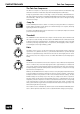
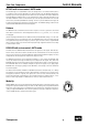
Detector/EXT SC, OFF, FILTER
Use this three-stage switch to determine how the compressor’s sidechain is to be fed, i.e. the
internal chain where all processing takes place. In the center position, “OFF”, the audio signal
feeds the sidechain, so the compression affects the whole frequency spectrum. This position
is the default setting.
In the upper position, “EXT SC” (short for “external side chain“), the SIDECHAIN input on the
rear panel is active. The compressor is, thus, controlled according to the signal fed into the
sidechain input. In other words, the compressor can be used to process the input signal while
being controlled with a modified or totally different signal. For example, you could make a
copy of the original signal, filter it with an EQ and then feed it into the sidechain so that the
compressor only responds to a specific part of the signal (or vice versa, if the frequencies are
cut instead of boosted). Another common use of the sidechain is ducking. For example, if you
wanted to separate the bass drum from the bass guitar you could compress the latter with the
former by feeding the bass drum into the sidechain. The bass guitar would then “duck” every
time the bass drum kicks in, providing more precision to the low end. Using this technique,
you could also give rhythm to sound pads, so that they swing a bit more.
To activate the Transpressor’s internal filters to control the sidechain, select the lower posi-
tion, “FILTER”. Refer to section “Detector/1, 2, 3” for further details.
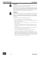
Detector/1, 2, 3
The internal frequency filters of the Twin Core Compressor are a very convenient alternative
to external processors. You have two low-pass and one bandpass filter at your disposal, so
that compression can be focused at specific frequency ranges. Do note that in order for the
specific filter to be active, the EXT SC, OFF, FILTER switch has to be set to “FILTER”.
LP1 activates a low-pass filter with cut-off frequency set at 100 Hz and a 18 dB/octave slope.
The compressor responds only to low frequencies.
LP2 activates a low-pass filter with cut-off frequency set at 680 Hz and a 18 dB/octave slope.
Processing affects only the low and mid frequency ranges.
BP activates a bandpass filter with cut-off frequencies set at 800 Hz and 3.1 kHz and a 12 dB/
octave slope. This filter is ideal to focus on vocals.
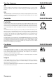
GR meter
The GR meter indicates the signal’s gain reduction as a result of the compression. Since the
meter indicates a reduction in gain, it works downwards. The 10-segment LED meter ranges
from 1.5 dB to -21 dB.
When the maximum reduction — corresponding to the highest signal level — indicates, for
example, -8 dB, you should set the MAKE UP control to a value around +8 dB to achieve the
best results (refer to “MAKE UP” on page 15).
OUT meter
The OUT meter indicates the output level after passing through all control elements. The
meter ranges from +18 dB to -9 dB. Even though the MAKE UP and PARALLEL MIX controls
have the most impact on the output level, all other settings in the different modules also have
an effect on the overall level. The OUT meter has a peak hold LED that indicates and holds, for
about one second, the last peak value. This indicator makes it easier to read peak levels.