
User Manual


9
Transpressor
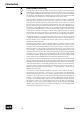
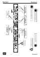
Rear Panel
Connections & Switches
Signal Connections
Turn off the unit before connecting or disconnecting any cable or equipment to it. Otherwise
you risk the possibility of damaging your ears or equipment.
Input and Output Electronics
The input and output electronics of the Transpressor use bridge circuits that keep the signal
flow constant, regardless of malfunctioning equipment and power outages (Hard Bypass).
The bridge circuits rely on high-quality relays. Contact surfaces are gold-plated to provide
better conductivity, and encapsulated to avoid external influences due to climate or atmo-
spheric conditions.
TRS and TS sockets (1/4" stereo and mono jacks)
The Jack sockets at INPUT and OUTPUT 2 are balanced TRS. Use stereo jack connectors only
to establish balanced connections. By using mono jacks you establish unbalanced connec-
tions. The SIDECHAIN input socket is unbalanced. You can use either stereo or mono jacks,
this wiring is always unbalanced.
XLR sockets
All signal connections are made via balanced XLR connectors. Inputs are always female and
accept male connectors; outputs are always male. All in all, a very comprehensible principle.
Power connection and fuse
Connect the power cord to the rear MAINS INPUT socket. Transformer, power cord and case
connection conform to VDE, UL and CSA requirements.
The fuse is accessible from outside and placed right behind the flap right from the socket.
Fuse ratings are 315 mA slow blow (
230
volts) or 630 mA slow blow (
115
volts).
Voltage Selector
The rear panel VOLTAGE selector sets the local line voltage (115 V position: 110-120 volts/6o Hz,
230 V position: 220-240 volts/50 Hz). The diagram shows the correct switch position for 230 V
power supply.
BEFORE you connect electrical power make sure that the VOLTAGE selector setting reflects
the correct local power line voltage.
Power Switch
Use the POWER switch on the rear panel to turn the unit on or off. The blue ON LED above the
GR LED on the front panel will light up as soon as you switch the unit on, regardless of the
position of the TD ON and COMP ON push buttons.
GND Lift
The rear panel GND LIFT switch eliminates hum by separating the internal ground from the
unit’s housing ground. Hum can, for example, result when this unit’s housing has a common
ground connection with other devices that might have a different ground potential. The
switch is usually deactivated to retain the shielding of the housing.
0
I
GND LIFT
GND LIFT
GND
0
I
230V ~50Hz
315mA slow
115V ~60Hz
630mA slow
VOLTAGE | FUSE