
8-Channel Monitor Volume Controller User Guide / Owners Manual

6
Volume 8
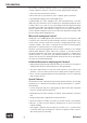
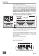
Rear Panel
Power Supply, On/Off Switching
Be sure before connecting the Volume 8 to power that the rear-chassis voltage
supply is switched to the proper local rating (either 230 or 115 volts). Above
all, before connecting any machines, take additional care to power down
all those to be used (and move the rear-chassis power supply switch of the
Volume 8 to the “down“ position). Finally, always use the following procedure
in powering up your assembly: Always power on your Volume 8 first before
the power amp or active speakers. When powering down, always power off
the power amp or active speakers before your Volume 8. Not following this
sequence can result in ear or speaker damage from high level discharges.
The Volume 8 comes with a standardized 3-pole (grounded) IEC power cord
which is connected to the main power input socket (Mains Input).
Mains Input
220-240V
~50Hz
Fuse: 200mA
110-120V
~60Hz
Fuse: 400 mA
AVIS: RISQUE DE CHOC ÉLECTRIQUE - NE PAS OUVRIR
RISK OF ELECTRIC SHOCK
DO NOT OPEN
CAUTION
Voltage Setting / Fuse Rating
230V
ELECTRICAL PIN CONFIGURATION COMPLIES WITH
TASCAM STANDARD. REFER TO MANUAL FOR DETAILS.
ELECTRONICALLY BALANCED
INPUTS AND OUTPUTS (+4dB).
Sound Performance Lab
Niederkrüchten, Germany
www.soundperformancelab.com
Serial Number
MADE IN GERMANY
TO REDUCE RISK OF FIRE OR ELECTRIC SHOCK DO
NOT EXPOSE THIS UNIT TO RAIN OR MOISTURE.
DISCONNECT MAINS BEFORE REMOVING COVER.
THIS EQUIPMENT MUST BE EARTHED.
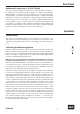
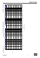
DB 25 WIRING WARNING
Inputs 1 to 8Outputs 1 to 8
13 12 11 10 9 8 7 6 5 4 3 2 1
25 24 23 22 21 20 19 18 17 16 15 14
M C HM C HM C HM C HM C HM C HM C HM C H
1 2 3 4 5 6 7 8
M = GND, C = Cold (-), H = Hot (+)
The electrical pin configuration of the balanced DB 25 input and output
sockets comply with the TASCAM standard (see graphic below). The nominal
input level is +4 dB, other levels are transmitted 1:1.
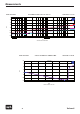
DB 25 to XLR, TRS or RCA multicore cables are required for connection of input
and output signals. The eight channels of the DB 25 connector at one side
are routed to eight single XLR, TRS or RCA connectors on the other side. The
channel configuration is free (input = output). Here are some common multi-
channel configurations:
SMPTE/ITU: L/R/C/LFE/LS/RS/L(t/o)/R(t/0)
DTS: L/R/LS/RS/C/LFE/L(t/o)/R(t/0)
Film: L/LS/C/RS/R/LFE/L(t/o)/R(t/0)
SDDS: L/LC/C/RC/R/LFE/LS/RS