
Brochure


t SELECTION PROCEDURE
Page 2 — BULLETIN 10-10
The following procedure should be used when selecting a
Sporlan TEV:
1. Determine the liquid temperature of the refrigerant
entering the valve.
The TEV capacity tables on pages 4 to 8 are based on a
liquid temperature of 100°F for R-22, R-134a, R-401A,
R-402A, R-404A, R-407C, R-408A, R-409A, R-410A, and
R-507. For other liquid temperatures, apply the correction
factor given in the tables for each refrigerant. For example
see Table B.
2. Determine pressure drop across valve.
The pressure drop correction factors are based on standard
liquid temperature and pressure drop. The standard pres-
sure drop is dependent on the evaporator temperature. To
determine the pressure drop, subtract the saturated pressure
equivalent to evaporator temperature from the condensing
pressure. The condensing pressure used in this calculation
should be the minimum operating condensing pressure
of the system. From this value, subtract all other pressure
losses to obtain the net pressure drop across the valve. Use
this value to determine the pressure drop correction factor.
For example see Table C. Be sure to consider all of the fol-
lowing possible sources of pressure drop:
1. Friction losses through refrigeration lines including the
evaporator and condenser.
2. Pressure drop across liquid line accessories such as a
solenoid valve and filter-drier.
3. Static pressure loss (gain) due to the vertical lift (drop) of
the liquid line.
4. Pressure drop across a refrigerant distributor if used.
Refer to Bulletin 20-10 for information on refrigerant distributors.
3. Select valve from the capacity tables.
Select a valve based on the design evaporating temperature.
If possible the valve capacity should be equal or slightly
exceed the design rating of the system. Be sure to apply the
appropriate correction factors for liquid temperature and
pressure drop. Once the desired valve capacity has been
located, determine the nominal capacity of the valve from
the tables’ second column. On multiple evaporator systems,
select each valve on the basis of individual evaporator
capacity. For example see Table A.
4. Determine if an external equalizer is required.
The amount of pressure drop between the valve outlet and
bulb location will determine if an external equalizer is
required. Refer to Bulletin 10-9 for further information on
this subject.
5. Select body type.
Select the body type according to the style connections
desired. For complete specifications on each TEV type
including nominal ratings, refer to pages 9 to 11.
6. Select the Sporlan Selective Thermostatic Charge.
Select the charge according to the design evaporating tem-
perature from the Table on page 3. Refer to Bulletin 10-9
for a complete discussion of the available Sporlan Selective
Thermostatic Charges.
Selection Example – Refrigerant 22
Application: medium temperature refrigeration
Design evaporator temperature . . . . . . . . . . . . . . . . . . . . 20°F
Design condenser temperature . . . . . . . . . . . . . . . . . . . . 95°F
Refrigerant liquid temperature . . . . . . . . . . . . . . . . . . . . . 70°F
Design system capacity . . . . . . . . . . . . . . . . . . . . . . . . . . . 1 ton
Available pressure drop across TEV:
Condensing pressure (psig) . . . . . . . . . . . . . . . . . . . . . . . 182
Evaporating pressure (psig). . . . . . . . . . . . . . . . . . . . . . . . 43
139
Liquid line and accessories loss (psi) . . . . . . . . . . . . . . . – 4
Distributor and tubes loss (psi)
Q . . . . . . . . . . . . . . . . . – 35
100
Refrigerant liquid correction factor . . . . . . . . . . . . . . . . . . 1.17
Pressure drop correction factor . . . . . . . . . . . . . . . . . . . . . 0.89
Use the following formula to calculate TEV capacity:
TEV Capacity = TEV rating x CF liquid temperature x CF pressure drop
EGVE-1 has valve capacity of: 1.09 x 1.17 x 0.89 = 1.14 Tons at 20°F
evaporating temperature, 100 psi pressure drop and 70° liquid
temperature.
Thermostatic charge (from table on page 3): VC
W
Selection:
EGVE-1-C 3/8” x 1/2” x 1/4” ODF x 5’
Q An externally equalized valve must be used on evapo-
rators employing a refrigerant distributor due to the
pressure drop created by the distributor. In addition, an
externally equalized valve should always be used with air
conditioning thermostatic charges to reduce the possibil-
ity of thermostatic charge migration.
W Please note that the refrigerant charge designation in the
thermostatic charge (“V” in this case) is dropped when it
is incorporated into the valve model designation.
Table B
REFRIGERANT
LIQUID TEMPERATURE ENTERING TEV °F
0° 10° 20° 30° 40° 50° 60° 70° 80°
CORRECTION FACTOR, CF LIQUID TEMPERATURE
22
1.56 1.51 1.45 1.40 1.34 1.29 1.23 1.17 1.12
407C
1.69 1.62 1.55 1.49 1.42 1.35 1.28 1.21 1.14
Liquid Temperature
Table C
TEV Pressure Drop
EVAPORATOR
TEMPERATURE
°F
PRESSURE DROP ACROSS TEV (psi)
30 50 75 100 125 150 175 200
CORRECTION FACTOR, CF PRESSURE DROP
40°
0.55 0.71 0.87 1.00 1.12 1.22 1.32 1.41
20° & 0°
0.49 0.63 0.77 0.89 1.00 1.10 1.18 1.26
-10° & -20°
0.45 0.58 0.71 0.82 0.91 1.00 1.08 1.15
-40°
0.41 0.53 0.65 0.76 0.85 0.93 1.00 1.07
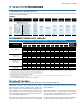
Table A
t
AIR CONDITIONING, HEAT PUMP and COMMERC
THERMOSTATIC EXPANSION VALVE
CAPACITIES for REFRIGERANTS - TONS
VALVE
TYPES
NOMINAL
CAPACITY
REFRIGERANT
22
RECOMMENDED THERMOSTATIC
VC, VCP100, VGA VZ, VZP40
EVAPORATOR TEMPERATURE °F
40° 20° 0° -10° -20° -40°
F-EF-G-EG
1/5
0.20 0.22 0.19 0.17 0.15 0.11
F-EF-G-EG 1/3
0.35 0.38 0.33 0.27 0.24 0.18
F-EF-G-EG 1/2
0.45 0.49 0.43 0.35 0.31 0.23
G-EG 3/4
0.75 0.82 0.71 0.68 0.61 0.45
F-EF-G-EG 1
1.00 1.09 0.95 0.86 0.77 0.57
F-EF-G-EG 1-1/2
1.60 1.74 1.52 1.22 1.09 0.81
Design Evaporating
Temperature
The valve capacity should equal or
slightly exceed the tonnage rating
of the system. (For complete R-22
capacity tables, see pages 4 and 5.)