
Install Instructions
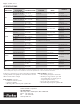

GENERAL – The oil level adaptor kits described below are
used to attach the Sporlan oil level control to the sightglass
connection on the compressor housing. In addition to the
adaptor fitting, the kits contain the necessary bolts, nuts,
O-ring, and sightglass (except AOL-R-1). All Sporlan oil level
controls have the same 7 bolt universal flange connection. The
adaptor kits permit installing the oil level control onto com-
pressors with various threads or mounting hole configurations.
INSTALLATION – The overall procedure is to remove the
existing sightglass on the compressor, install the oil level
adaptor in its place, and then attach the oil level control to the
adaptor. This procedure requires the following steps:
1. Follow the procedure suggested by the compressor man-
ufacturer if the procedure is available. Otherwise the
following steps are suggested.
2. Shut off the power to the compressor involved and close
the suction service valve, or other valves to isolate the
compressor.
3. Release the refrigerant pressure in the compressor by
opening an appropriate connection (for example, loosen
the connection on the low pressure control). Drain the
oil to a level below the bottom of the sightglass. This can
be done through a drain plug, or by pulling the oil out
through the filler connection with a pump.
4. Remove the sightglass from the compressor. This will
require unbolting or unscrewing the sightglass.
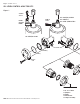
5. Attach the adaptor to the compressor. The AOL-A and
AOL-C are machine threads and are sealed with an O-ring.
The O-ring will seal better if it is lubricated with a light film
of oil. The AOL-R-1 bolts to the compressor. See Figure 1.
NOTE: The bolt holes on the sightglass and oil level con-
trol are not equally spaced. Be sure to line the holes up
properly. The mark on the edge of the flange indicates the
top.
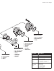
6. Attach the sightglass plate to the oil level control. The side
of the sightglass plate with the O-ring groove goes toward
the flange on the oil level control. The sightglass may be
attached to either arm of the oil level control. Bolts are
provided, as well as an O-ring and quad ring. Since both
of the mating parts contain a groove, the use of the O-ring
and quad ring combination permits getting a proper seal.
Tighten the bolts and nuts to approximately 6 ft.-lbs.
torque.
7. The oil level should always be adjusted to the level spec-
ified by the manufacturer. The oil level control can be
adjusted before use by following the instructions given in
Sporlan Bulletin 110-10 or Form SD-129 supplied with the
oil level control.
8. Attach the oil level control (with sightglass) to the adaptor
(already installed) using the bolts, nuts, and O-ring pro-
vided.
9. Connect the oil supply line from the reservoir to the flare
fitting on top of the oil level control.
10. Some oil level controls incorporate an oil equalization
fitting. If the system requires this connection, connect the
3/8” flare fitting on the side of the oil level control to the
oil equalization line. If the equalizer is not required, a cap
must be installed.
11. Refill the crankcase with oil to the proper level. Evacuate
the compressor and oil level control. Open the service
valve to pressurize the compressor and oil level system.
Test for leaks. Then start the unit following the manufac-
turer’s recommendations.
Sporlan oil level controls are listed by Underwriters
Laboratories for use with Refrigerants 134a, 22, 404A, 407C,
and 507. The controls have a maximum rated pressure of 650
psi (45 bar).
Oil Level Adaptor Kits
Installation Instructions
Bulletin 110-11, March 2014
ADAPTOR