
Installation guide

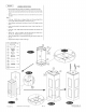
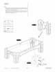
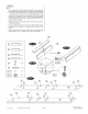
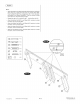
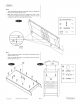

FIG.
6:
«
Attach
the
Right
Board
(#25)
to
the
Assembly
using two
Locking
Pins
(#47)
and
two
Dowels
(#48)
per
board.
«
Note:
Insert
Locking
Pin
(#47)
into
Locking
Screw
(#A17)
which
has
been
pre-installed
in
the
Bottom
Board(#22)
.Then
turn
arround
Locking
screw
(#A17)
in
clock
wise
till
pin
is
locked.
A17
FIG.
7:
«
Attach
the
Back Board
(#28)
to
the
Assembly
using
fifteen
Screws
(#35)
as
shown
in
Fig.
7.
«
Attach
the
Header
Board
(#17)
to
the
Assembly
using
two
Screws
(#34)
as
shown
in
Fig.
7A.
G5)
avenue
=
(15)
®
eer
<sioan
= )
(1)
©2009
Sportcraft,
Lid.
4-1-32-931
PL
(Continued
on
the
next
page.)
www.sportcraft.com