
Installation guide
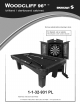

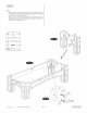
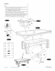
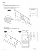

FIG.
4:
Screw
Locking
Pin(#47)
into
Plastic
Screw(#A19)
which
has
been
pre-installed
in
the
Front
Board(#23).Then
attach
Bottom
Board(#22)
to
one
Front
Board
(#23) using
one
Locking
Pin
(#47)
forming
an
“L”
shape
as
shown
in
Figs.
4A, 4B,
and
4C.Note:
Make
sure
the
arrow
on
the
screw
point
out
to
Locking
Pin
#47).Insert
Locking
Pin
(#47)
into
Locking
Screw
(#A17)
which
has
been
pre-installed
in
the
Bottom
Board(#22)
.Then
turn
arround
Locking
screw
(#A17)
in
clock
wise
till
pin
is
locked.
Repeat
this
step
to
Per
Locking
Pin
(#47)
and
Plastic
Screw(#A17),
Locking
Screw
(#A19)
Attach
one
Bottom
Board
(#22)
to
one
Front
Board
(#23)
using
one
Locking
Pin
(#47)
forming
an
“L”
shape
as
shown
in
Figs.
4A, 4B,
and
4C.
Insert
Locking
Pin
(#47)
and
six
Dowels
(#48)
on
the
Right
Board
(#25)
as
shown
in
Fig.
4.
Repeat
the
same
for
Left
Board
(#24).
Sr
PLASTIC
SCREW
ik
&
5
!
*¢
<=
¢——
&
Com
cS
€
aN
@
We
4-1-32-931
PL
(Continued
on
the
next
page.)
P.7
©2009
Sportcraft,
Lid.
www.sportcraft.com