| Tae 8 | OC ni SHANAHAN sh Ha DO NOT RETURN TO STORE NO DEVOLVER A LA TIENDA SPORTCRAFT: (800) 526-0244 1-1-34-832 SS Assembly, Instructions and Rules 313 Waterloo Valley Road / Budd Lake, NJ 07828 instrucciones de ensamblaje y reglas / www.sporicraft.
IMPORTANT SAFETY INSTRUCTIONS INSTRUCCIONES IMPORTANTES DE SEGURIDAD 1. Read all instructions - All the safety and operating instructions should be read carefully before this turbo hockey game is played. Lea todas las instrucciones — todas las instrueciones de seguridad y operacién se deben leer con cuidado antes de utilizar este juego de hockey. 2. Caution - This is not a toy and is intended for use by or under the supervision of adults.
Congratulations! hours of enjoyable Turbo Hockey! ./ « We hope you will have many use with your new iFelicitaciones! jNosotros esperamos que este nuevo juego de Turbo Hockey Sportcraft le proporcione muchas horas de diversién! Sportcraft PLEASE KEEP YOUR INSTRUCTIONS! jPOR FAVOR GUARDE ESTAS INSTRUCCIONES! « Your Model number is necessary should you need to contact us. * Su numero de modelo es necesario en caso de que deba comunicarse con nosotros.
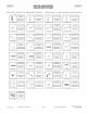
PARTS IDENTIFIER IDENTIFICACION DE LAS PIEZAS (Add a Check (\ ) to the box!_!to indicate receipt of each part.) G) _ ROUNDED LEG PANEL (@) LEFT LEG PANEL PANEL DE PIERNA REDONDEADO. 9-3-34-8325S01 (4) @ 1 tee 2) (Afiada una marca (V ) a la caja ti para indicar el recibo de cada pieza.
ACCESS ORIES/Pre-Installed Parts (AVAILABLE FOR PURCHASE ONLINE. ACCESORIOS/Piezas preinstaladas (DISPONIBLE PARA COMPRA POR INTERNET.
FIG. 1: LEG ASSEMBLY FIG. 1: ASAMBLEA DE PIERNA Connect one Left Panel (#2) and one Right Panel (#3) to one Middle Leg Panel (#4) using three Screws (#23) per Leg Panel. See Fig.1. Fijar un panel izquierdo (no. 2) y un derecho (no. 3) al panel de pierna de centro (no. 4) con tres tornillos por tablero. Ver la figura 1. Slide one Rounded Leg Panel (#1) into the grooves of the leg panel assembly and attach using two Screws (#22). See Fig. 1 Deslizar un panel de pierna redondeado (no.
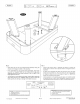
CRORCROIORC FIG. 2: FIG. 2: « Attach each Apron Corner (#29) between one Side Apron one End Apron (#6) using six Screws (#22) per Corner. « Attach the Puck Return Boxes two Screws (#22) per Box. 4-1-34-832 SS (#30) to the End Aprons (Continued on the next page.) (#8) and Fijar un esquina de tabla (no. 29) entre una tabla lateral (no. 8) y una tabla de extremo (no. 6) usando seis tornillos (no. 22) por esquina. (#6) using Fijar las cajas para la devolucidn del disco (no.
= (2) = (12) (0) == (0) = (2) =(4 = (12) = (8) FIG. 3: (2) SOX =e) bes = (1) FIG. 3: Attach the Leg Support Board - B (#10) to the Leg Support Board -A (#9) using four Screws (#23). Fijar el tablero de soporte de pierna - B (no. 10) al tablero de soporte de pierna - A (no. 9) utilizanco cuatro tornillos (no. 23). Attach two Leg Support Boards - C (#11) to the underside of the Leg Support Board - A (#9) using two Bolts (#20) and two Washers (#17) per Board - C.
Slide Deslizar FIG. 4: FIG. 4: « Slide each Leg Support Board assembly on the Side Aprons. « Attach them to both Side Aprons using four Washers (#20) and four Bolts (#18) for each Leg Support Board assembly. 4-1-34-832 SS between (Continued on the next page.) Deslizar cada asamblea del tablero de soporte bloques encontrados sobre las tablas laterales. the blocks found de pierna entre los Fijarlos a ambas tablas laterales usando cuatro arandelas (no. 20) y cuatro pernos (no.
FIG. 5: FIG. 5: Place each leg onto the Leg Support Board assembly direction of the diagram sticker on the assembly. facing Colocar cada pierna sobre la asarmblea del tablero de soporte de pierna segun la direccién de la etiqueta adhesiva de diagrama sobre la asamblea. the From underneath the Leg Support Board assemblies, attach each Leg with two Washers (#19) and two Bolts (#16) in the holes diagonally across from each other as shown in Fig. 5A. NOTE: Only finger-tighten at this time.
FIG 6: « ¢« FIG 6: Insert two Washers (#19) and two Bolts (#16) in the remaining holes of each Leg Support Board as shown in Figures 6 and 6A. Go back and tighten all the bolts completely the Wrench Ahora regresar y apretar todos los pernos completamente usando la llave inglesa (no. Ad). (#A4). 4-1-34-832 SS using Encartar dos arandelas (no. 19) y dos pernos (no. 16) en los agujeros restantes de cada tablero de soporte de pierna segun las figuras 6 y 6A. (Continued on the next page.) . .
Scorer opening Apertura del marcador WARNING: BE CAREFUL NOT TO PINCH YOUR FINGERS WHILE LOWERING THE CABINET. NOTE: Make sure the Blower wire is not dangling as the cabinet is lowered, or damage to the wire may occur. ADVERTENCIA: ASEGURARSE NO PELLIZCAR SUS DEDOS BAJANDO EL CAJON. NOTA: Asegurese que el cable de soplador no pende cuando el cajén es bajado, o el dafio al cable puede ocurrir. FIG. 7: FIG. 7: the TO PINCH YOUR FINGERS WHILE LOWERING THE CABINET.
(eevee = (8) FIG, 8: = FIG. 8: From underneath the table, attach the Cabinet to the Leg Support Boards lL (Q)-« - B (#10) using four Bolts (418) and four Washers (#20) * per Board B. hrewese ss De abajo la mesa, fijar el cajon al tablero de soporte de pierna - B (no. 10) utilizando cuatro pernos (no. 18) y cuatro arandelas (no. 20) por tablero B. (Continued on the next page.) | P.12 (Siga a la pagina siguiente.
FIG. 9: FIG. 9: « NOTE: While attaching the Leg Support to the Cabinet, itis important to gently lift up on the End Aprons to eliminate any gap between the Aprons and the Cabinet. See Fig. 9B. ° « From underneath the table, attach the Cabinet to the End Aprons (# 6) using two Bolts (#18) and two Washers (#20) per End Apron. 4-4-34-832 SS (Continued on the next page.
English @2)
A3 LED wire (Pre-installed Cable pre-instalado) * — ~ LED wire .. (Pre-installed Cable pre-instalado) (Pre-installed Cable pre-instalado) x A3 (Pre-installed Cable pre-instalado) FIG. 11: FIG. 11: « Thread the wire from the LED Scorer (#24) through the opening the top rail of the cabinet and attach using two Bolts (#21). « Cover the openings in the scorer with two Screw Caps (#28). « From underneath the table, insert the scorer wire Adapter #A8) into the Control Box (#33).
TABLE MAINTENANCE TABLE SURFACE (Mesa) PUCKS (MANTENIMIENTO DE LA MESA) Wipe playing surface with a clean clothbefore and after each use.While table is on, vacuum gently with a soft brush attachment on a vacuum cleaner. Limpie la superficie de ‘juego con -un pafio limpio antes y después. de usarla.Con usando el aditamento de cepillo de la aspiradora.
SPORTCRAFT&p sportcrart & LIMITED WARRANTY GARANTIA LIMITADA Limited Warranty Sportcraft, Ltd. (the “Company”) warrants the Product to be free from defects in workmanship and materials under normal use and conditions FOR APERIOD OF 90 DAYS FROM THE DATE OF ORIGINAL PURCHASE in the United States and Canada.
Attention: We need your help! Our goal is to produce the finest product possible. Unfortunately, there are times when a product malfunctions or a part breaks. We are happy to replace the part, and this can be done by ordering from our web site or by calling our toll free number. However, we also want to know why the part malfunctioned or broke so that we can improve it in the future. To that end, please take a picture of the broken part and e-mail it to us at photos@ sportcraft.com.
> Atencion: jNecesitamos su ayuda! Nuestro objetivo es de producir el mejor producto possible. Lamentablemente, hay veces cuando un producto funciona mal o una pieza se rompe. Somos felices sustituir la pieza, y esto puede ser hecho por pidiendo sobre nuestro sitio web o por llamando a nuestro numero de teléfono gratis. Sin embargo, también queremos saber /a razon que la pieza funcioné mal o se rompié de modo que nosotros podamos mejoraria en el futuro.