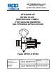
AUTOPRIME XF300 & 400 CENTRIFUGAL PUMPS OPERATORS INSTRUCTIONS XF RANGE OF EXTRA FLOW CENTRIFUGAL PUMPS FOR VACUUM ASSISTED SELF PRIMING APPLICATIONS Types XF300 & XF400 SPP Pumps Limited Crucible Close Mushet Industrial Park Coleford, Glos ENGLAND GL16 8PS Telephone: ++44(0) 1594 832 701 Fax: ++44(0) 1594 836 300 Document No: Revision No: Revision Note No: W77-009E 3 R 39552 Date Issued.
DECLARATION OF CONFORMITY We SPP Pumps Limited Of Crucible Close Mushet Industrial Park Coleford Gloucestershire England GL16 8PS Declare that: Equipment: Model/Type: Serial Number: DIESEL DRIVEN CENTRIFUGAL PUMPS XF300 & XF400 As shown on the Pump Nameplate in accordance with the following Directives: 2004/108/EC The Electromagnetic Compatibility Directive and its amending directives 2006/42/EC The Machinery Directive and its amending directives have been designed and manufactured to the follow
Operators Instructions for XF300 & XF400 Range Centrifugal Pumps Manual No/Rev W77-009E / 2 CONTENTS 1. GENERAL INFORMATION & SAFETY INSTRUCTIONS .. 4 2. TRANSPORT HANDLING & STORAGE INSTRUCTIONS 5 2.1 Transport ................................................................................................. 5 2.2 Handling .................................................................................................. 5 2.3 Storage .....................................................................
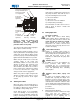
Manual No/Rev W77-009E / 2 Operators Instructions for XF300 & XF400 Range Centrifugal Pumps INTRODUCTION This manual gives the safety, installation, operation and maintenance instructions for pumps in the SPP Pumps’ AUTOPRIME XF range of horizontal, end suction, centrifugal pumps for vacuum assisted self priming applications. Instructions and statements contained within this handbook are given with our best intentions and are correct at the time of compilation. They are subject to alteration at any time.
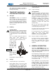
Operators Instructions for XF300 & XF400 Range Centrifugal Pumps This symbol gives warning of a hazard to the pump itself, which in turn could cause a risk to personal safety. 2. TRANSPORT HANDLING & STORAGE INSTRUCTIONS 2.1 Transport cast iron parts, and should not be removed until final installation. 2.3.2 Fill the seal and bearing housings with recommended oil to ensure that the shaft, seal and bearings remain rust free.
Manual No/Rev W77-009E / 2 Operators Instructions for XF300 & XF400 Range Centrifugal Pumps The discharge branch is positioned at 45° above the centre of the pump volute. This allows the fitting of a ball or flap type nonreturn valve to give a horizontal discharge. The pump is centreline mounted and the volute is provided with an access point for examination of the impeller. The pump has been designed for use with an automatic priming system typically one using a vacuum pump with a priming tank.
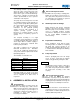
Operators Instructions for XF300 & XF400 Range Centrifugal Pumps 4.4 4.5 a) Lateral Alignment Mount a dial gauge on the motor shaft or coupling with the gauge running on the outer machined diameter of the pump coupling. Turn the motor shaft and note the total indicator reading. b) Angular Alignment Mount a dial gauge on the motor shaft or coupling to run on a face of the pump coupling as near the outside diameter as possible. Turn the motor shaft and note the total indicator reading.
Manual No/Rev W77-009E / 2 Operators Instructions for XF300 & XF400 Range Centrifugal Pumps clean to ensure that site debris is not drawn into the pump when it is commissioned. 4.7 4.9 The pump is designed to be secured to a substantial baseplate to maintain the shaft alignment between the driver and the pump. The baseplate should be securely located on level ground or mounted on foundations. The shaft alignment should be checked again before commissioning and putting the pump into operation.
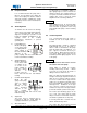
Operators Instructions for XF300 & XF400 Range Centrifugal Pumps Mechanical Seal Oil Filler Plug Manual No/Rev W77-009E / 2 head requirements. Bearing Oil Filler/Breather If the pump is operating at its normal speed, the pump should be shut down at once if any of the following defects are found: Mechanical Seal Oil Level Sight Glass Bearing Oil Running Level Sight Glass a) b) c) d) Recommended corrective action for these faults is given in Section 7 Faults and Remedial Action.
Manual No/Rev W77-009E / 2 Operators Instructions for XF300 & XF400 Range Centrifugal Pumps contaminated replace the mechanical seal. b) Bearing Temperature Check the outer bearing housing temperature does not exceed 80degC. c) Bearing Lubrication Check that the oil level is visible in the running level sight glass and look for evidence of contamination. Top up with 0.1 litres of oil if required, check level again when pump has run for 5 minutes, top up with 0.
Operators Instructions for XF300 & XF400 Range Centrifugal Pumps maintenance area. Recommended Maintenance Schedule PERIOD It is important to ensure the suitable lifting equipment is available and that the work is carried out in a clean area. TASK Check the bearing lubricating oil level in the bearing housing running sight glass and top up oil if needed with 0.1 litres of oil. Check the mechanical seal lubrication oil level and top up if required.
Manual No/Rev W77-009E / 2 d) Operators Instructions for XF300 & XF400 Range Centrifugal Pumps Initial Lubrication: Oil chambers on these pumps are emptied for transport and must be filled with the specified oil to the required level prior to running. After the first 50 hours of operation, drain off a sample and check for any oil contamination. If any contamination is found, the oil is to be changed. 6.5 i) Wipe the seal recess clean, lubricate the ‘O’ ring with a light smear of seal lubricating oil.
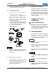
Manual No/Rev W77-009E / 2 Operators Instructions for XF300 & XF400 Range Centrifugal Pumps b) casing B10. Insert two of these screws into the jacking screw positions and gently tighten to separate the bearing housing A10 from the volute casing. drive end bearing cap A20 Remove the bearing housing complete with shaft and impeller from the volute casing and take this rotating assembly to a clean area for further disassembly.
Manual No/Rev W77-009E / 2 Operators Instructions for XF300 & XF400 Range Centrifugal Pumps wrapped for storage. b) Check the shaft F10 for straightness by mounting between centres and measuring the run-out with a dial gauge at the coupling, bearings, centre, seal and impeller positions. The run-out should not exceed 0.05 mm in any of the positions measured.
Operators Instructions for XF300 & XF400 Range Centrifugal Pumps tighten the capscrew to 350 Nm. Fit the cover plate A100 and if removed, insert oil level sight glasses A230, drain plug A140 and overflow plug A180. Fill the housing with bearing oil to the correct level. e) Rotate the impeller and visually confirm that it runs true, if not remove, clean all parts and reassemble. Back Wear Plate Assembly Clean the ‘O’ ring grooves lubricate and place the ‘O’ ring D40 into the groove.
Manual No/Rev W77-009E / 2 Operators Instructions for XF300 & XF400 Range Centrifugal Pumps 7. FAULT FINDING & REMEDIAL ACTION 7.1 Priming System Faults Pump Fails to Prime Check pump drain valve is closed. Check vacuum pump is operating, if not rectify or replace the pump. Disconnect vacuum hose and take a vacuum reading, refit the hose and fit vacuum gauge to the pump inlet and take another vacuum reading. Are vacuum gauge readings the same? YES Check the suction hose for internal collapse.
Operators Instructions for XF300 & XF400 Range Centrifugal Pumps 7.2 Manual No/Rev W77-009E / 2 Pump Fault Finding POTENTIAL FAULT OR DEFECT: Insufficient liquid delivered. Liquid delivered at low pressure (Fails to achieve the required delivery head) Loss of liquid after starting. Excessive vibration. Pump bearings run hotter than normal. PROBABLE CAUSES Speed too low. Speed too high.
Manual No/Rev W77-009E / 2 Operators Instructions for XF300 & XF400 Range Centrifugal Pumps 8. Supplementary Documents 8.
Manual No/Rev W77-009E / 2 Operators Instructions for XF300 & XF400 Range Centrifugal Pumps 8.2 Parts List ITEM DESCRIPTION PART No. QTY A10 Bearing Housing 21399.123 1 A20 Bearing Cap Drive End 21396.123 1 A30 Oil Seal 1 C20 Washer M20 x 5 08035.221 1 A40 Brg Cap Non Drive End 21397.123 1 C30 Screw Soc M20 x 95 15644.259 1 A50 Oil Seal 110mm 1 C40 Cap Plastic 22612-411-735-7 1 A60 Gasket Bearing Cap 21394.
Manual No/Rev W77-009E / 2 8.3 Operators Instructions for XF300 & XF400 Range Centrifugal Pumps Pump Data Pump Size XF300 XF400 DN 21697 DN21856 Pump Weight Approx. 450 kg TBA Maximum Working Pressure 13 bar 9 bar 2000rpm 1800rpm Dimensions as per General Arrangement Maximum Permitted Operating Speed Direction of Rotation Clockwise when viewed on the drive end Impeller Back Clearance 1 to 2 mm Impeller Front Clearance 0.38 to 0.
Manual No/Rev W77-009E / 2 Operators Instructions for XF300 & XF400 Range Centrifugal Pumps 9. ADDITIONAL INFORMATION 9.1 Standard Metric Nut and Bolt Torque Recommendations This information is for reference only. The user must check that the torque figures listed here are applicable to the fasteners used. Nuts and bolts should be neither under nor over tightened. Approximate Torque (Nm) for Bolt Diameters: Grade of Bolt M5 M6 M8 M10 M12 M16 M20 M24 M30 M36 4.6 2.7 4.
Manual No/Rev W77-009E / 2 Operators Instructions for XF300 & XF400 Range Centrifugal Pumps Pump Maintenance Records: Date Summary of Work Done: Our policy is one of continuous improvement and we reserve the right to alter specifications at any time Page 22 of 23
Operators Instructions for XF300 & XF400 Range Centrifugal Pumps Manual No/Rev W77-009E / 2 10. SPARES & SERVICE SPP Pumps Limited operate a comprehensive Spares and Service support network throughout the world, and can be contacted as follows: SPARES & SERVICE Telephone: For spare parts, supply only. ask for - For breakdowns, spare parts and on-site fitting, pump installation and commissioning, and service contracts. ask for For breakdowns outside office hours.