
Manual

Operators Instructions for
XF300 & XF400 Range Centrifugal Pumps
Manual No/Rev
W77-009E / 2
Our policy is one of continuous improvement and we reserve the right to alter specifications at any time
Page 13 of 23
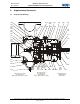
casing B10. Insert two of these screws into
the jacking screw positions and gently
tighten to separate the bearing housing A10
from the volute casing.
Remove the bearing housing complete with
shaft and impeller from the volute casing
and take this rotating assembly to a clean
area for further disassembly.
b) Removal of the Impeller
Support the rotating assembly securely and
ensure that suitable lifting facilities are
available.
Remove the plastic cap C40 from the centre
of the impeller C10 to give access to the
impeller retaining screw C30.
Use the drive shaft keyway to prevent the
impeller from turning and loosen the
impeller retaining screw C30.
Using a soft faced mallet, gently tap the
impeller to free it from the tapered shaft. . If
the impeller is tight then the thread in the
centre of the impeller can be used to jack
the impeller free. Withdraw the impeller
using suitable lifting equipment. (The
Impeller weighs approximately 65kgs)
Extract the impeller key F100 from the shaft
and retain for re-assembly.
Do not remove the balance weights (if
fitted) from the impeller.
c) Removal of the Mechanical Seal
Push the seal retaining washer E30 along
the shaft by approximately 2mm to allow the
retaining ring E20 to be removed using a
small screwdriver. Withdraw the retaining
washer and the rotating seal assembly E10
from the shaft F10.
Undo the small screws E50 and remove the
seal retaining plate E40. Remove the static
part of the seal E10, ensuring that no
carbon flakes or chips remain.
d) Removal of the Shaft and Bearings
Remove the pump half coupling from the
shaft as per the coupling manufacturer’s
instructions.
Undo the ring nut F70 and remove the fan
F110 from the shaft F10
Remove the screws A70 and remove the
drive end bearing cap A20
Remove the screws A70 and remove the
non drive end bearing cap A40.
Using a suitable press, apply pressure to
the tapered end of the shaft and push the
shaft out from the bearing housing,
complete with the bearings. (The Shaft &
Bearings weigh approximately 90kgs)
Do NOT drive the shaft from the bearing
housing using hammer blows as this will
damage the bearings and prevent their re-
use.
The bearings may be cleaned and
examined whilst on the shaft.
e) To remove the bearings from the shaft:
Using a suitable ‘C’ spanner, remove the
drive end bearing locknut F60 from the
shaft F10.
Fit a split collar of the required size to
support the inner race of the drive end
bearings, mount in a press and apply
pressure to the drive end of the shaft. Push
the shaft out from the bearings.
The oil thrower F20 may be removed at this
stage by undoing the locknut F30 with a
suitable ‘C’ spanner.
Reverse the shaft and press the shaft out
from the non-drive end bearing F50. If this
bearing is stuck fast and if it is to be
replaced, heat may be applier to the bearing
to free it from the shaft and apply hammer
blows using a suitable drift. Take care not
to damage the shaft.
Bearing Specifications:
Drive End
7322 BECBM
Pump End
22224E - C3
Drive end bearings are fitted in universal
matched pairs and must be replaced in
pairs. Inspect the bearings for wear,
fractures, cracks, corrosion or other
damage that may necessitate bearing
replacement.
If the bearings are to be re-used, ensure
they are thoroughly flushed with white spirit
or similar cleaning fluid, dried and protected
to prevent any abrasive media from coming
into contact with the races and balls.
Bearings should be lightly oiled and