/ Cofimco Fan – Adjustable Hub / User Manual 03-11A
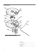
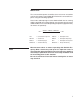
Fan Components 102 X14 W29 101 101 103 V11 104 102 X12 104 103 200 W29 VBA Figure 1—Typical Fan Assembly Order No.
Fan Assembly Instructions Note The following instructions apply to installations having straight bores or tapered output shafts without split taper bushings. It is convenient to preassemble the fan prior to installation on the driving shaft. 1—Select a large open area corresponding to the fan diameter. 2—Position the fan hub in the center of the work area with the center spool 101 oriented as shown in Figure 1.
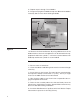
8—Repeat steps 3 through 7 for all blades. 9—Progressively tighten all blade clamp nuts X14 until the blades are barely able to move when twisting the blade. RETENTION SLEEVE Figure 3 TIGHTEN BLADE CLAMP BOLTS TO 100 FT·LB LUBRICATED TIGHTEN RETENTION SLEEVE NUT TO 40 FT·LB 10‑ Measure the final fan diameter. By using a different hole in the blade retention sleeves the fan diameter can be altered for the appropriate fit within the cylinder.
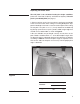
Adjusting Fan Blade Pitch Note The trial pitch is the calculated setting for design conditions (water rate , heat load, air density, and brake horsepower). The trial pitch is provided by SPX (see page 2). 1–Select a position on the fan circumference and rotate each blade to this common location when setting or checking blade pitch. Support the blade tip to maintain a common rotation plane while setting the fan pitch.
Fan Maintenance Preventative maintenance will prolong useful life and assure continued trouble-free operation. After the first week and subsequently at six month intervals: • Torque all hardware to specifications referenced in this manual. • Visually inspect the fan for airborne debris damage, contact with fan cylinder segments, and corrosive attack. Correct any situations determined detrimental to fan operation. • Remove any accumulated scale or dirt. • Clear blade drain holes at fan tip.
Motor Load The corrected horsepower should be close to but not exceed the contract horsepower specified by SPX. Determine corrected horsepower using the following equation. Actual volts and amperage must be obtained with the fan running and the specified rate of water flowing over the tower after the motor and Geareducer have reached operating temperature (approximately 30 minutes of operation).
7401 WEST 129 STREET | OVERLAND PARK, KANSAS 66213 UNITED STATES | 913 664 7400 | spxcooling@spx.com | spxcooling.com In the interest of technological progress, all products are subject to design and/or material change without notice. ©2008 SPX Cooling Technologies, Inc.